Journal of
eISSN: 2373-6437


New advances in ultrasound create this technology accessible to health care suppliers in daycare clinic. Ultrasound aids pain interventionist with real-time scanning and identification of the spine. There’s presently mounting proof that ultrasound improves patient safety enhances health care quality and reduces tending price. The evolving affordability of ultrasound has created this technology widely accessible. Ultrasound permits satisfactory scanning of the posterior elements of the spine and paraspinal soft tissues. Studies illustrated practicability and validity of ultrasound in spinal injections. According to the limitations and recommendations for injection safety, ultrasound training is essential, given its axial ability to spinal injection. The purpose of this clinical study is to provide an easy and safe procedure for ultrasonographic spinal injections.
The ultrasound is of particular interest in medicine, especially in the field of pain intervention. Pain injection initially was performed with the help of landmarks which caused many faults and complications.1 After, fluoroscopy was carried out and became the standard of care. Next, CT scan was introduced and there are studies that show longer-term efficacy for symptom relief after CT-guided injection.2 However, the fact that x-rays hazard always exists in these cases attracted the specialist’s attention to the ultrasound. There are other advantages for ultrasound compare to fluoroscopy that makes it adsorbent .For example, presentation of vessels and tissues, pleural movements and the portability of ultrasound which the probe easily moves by interventionist and gives the axial and longitudinal view and unlike fluoroscopy there is no need for assistant help to move the C-ARM and makes it applicable in the outpatient and its feasibility in cases where the patient cannot position properly as a result of internal or anatomical problems. It is arduous to obtain a proper view by the fluoroscopy as ultrasound is in the hands of the interventionist who hasn't met this limitation. Ultrasound is helpful in difficult surface anatomic landmarks or anatomical scatterings such as scoliosis or previous laminectomy with rods and screws where fluoroscopy cannot easily get an actual AP or real lateral view.3,4 Ultrasound is effective for caudal injections due to the anatomical differences in the sacral hiatus which causes errors in landmark or fluoroscopy methods.5,6 The number of first pass needle success rate will increase with ultrasound.4,7 Studies on spine sono-intervention and CT scan confirmation of the needle target location showed feasibility and validity of ultrasound in spine injections.8−12 Successful ultrasound guided spine injection needs preliminary information about spine anatomy, ultrasound device software , its capabilities and limitation, scanning technique and probe maneuvers. Ultrasound screening of the vessels and sometimes nerve will make needle insertion easier. Injection of the dose test and searching for its spread at or near the target point (note that in intravascular injection or wrong injection distribution of the test dose will not see) improve safety. Spine ultrasound due to its specific anatomy and the acoustic shadow of the vertebrae and the depth of the target structures is debatable. This is particularly evident in injections at L5.13,14 Spine ultrasound is a bit difficult due to the lack of clarity of skin marking and depth measurement chiefly for viewing the nerve roots. On the other hand, the anatomical difference of each vertebra made it more difficult.15 Despite the introduction of newer and less consuming times methods with the possibility of intravascular injection, there is still insufficient clinical evidence to prove safety of the ultrasound as a sole image guide intervention.10,16−21 The purpose of this study is to review the easiest and least complicated method of injection according to the capabilities and limitations of ultrasound. Therefore, in all injections, live fluoroscopy has been used after insertion of the needle in the desired location to confirm there is no intravascular injection.
For simple and safe spinal cord injections, you need to have enough information about spinal anatomy. Then you should be able to follow the anatomy on the ultrasound screen, the science of familiarity with sonoanatomy is the basis of ultrasound-driven spinal injections. In order to expedite learning and given the fact that most advocates have information about the lumbar region, lumbosacral sonoanatomy training will be discussed initially. Lumbar region is then compared to the thoracic and cervical regions. Finally, the simplest method of injection and needle maneuvering technique will be discussed.
The patient's position is usually prone, but injection can also be performed on the lateral decubitus, especially for the cervical medial branch block (MBB). There are many elements that should be considered first, for example, you should correctly calculate the vertebra by helping these landmarks: occipital promontory, C7 spinous process, the 12 rib, iliac crest,20−22 sacral promontory and vertebral artery (Figure 1). Then you must use a low frequency (5-2 MHz) curve probe and scan the spine column in both directions of the axial (transverse) and sagittal (longitudinal) views in the midline line and the paramidline (1-2 cm away from the middle line) First put the probe transverse on the midline and move it cephalocaudal to see spinous process and inter-spinous space of lumbar vertebras. In the axial view, the spinous process and laminae are hyper echoic and prevent the appearance of the spinal canal. This scan is usually used to determine the location and counting of the vertebrae (when it is not palpable due to obesity or previous surgery or other reason). The bony structures are in the form of a cat head in the axial plane: spinal cord is the cat's face, the articular processes are cat's ears and the transverse processes are the cat mustache but flavum ligament and epidural space are rarely seen (Figure 2) (Figure 3).
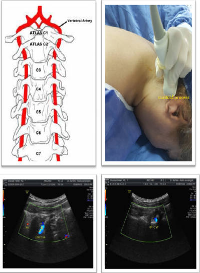
Figure 1 Effects of P sources and application rates on residual total N in soils after harvest.
Note: P sources ending with 1, 2, 3 and 4 indicates 0, 20, 40 and 60 kg P ha-1 respectively
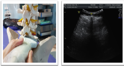
Figure 2 Effects of P sources and application rates on residual total N in soils after harvest.
Note: P sources ending with 1, 2, 3 and 4 indicates 0, 20, 40 and 60 kg P ha-1 respectively
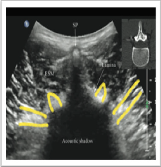
Figure 3 Effects of P sources and application rates on residual total N in soils after harvest.
Note: P sources ending with 1, 2, 3 and 4 indicates 0, 20, 40 and 60 kg P ha-1 respectively
Then turn probe 90° and put it longitudinally on the midline. At the sagittal view of the midline the hyper echoic spinous process are visible. A little farther and in paramedian line with heel in maneuver, you can see the space between the hyper echoic lamina as a hypo echoic acoustic window through which the neuraxial content are visible (Table 1) (Figure 4).22,23 After identifying the midline and paramidline, you can search for other structures needed for injection. If you rotate the probe to the left or right and move away from the lamina, you can see the articular process and zygapophyseal joint (Z joint), which is a hyperechoic line continuously and without interrupted gaps. And by moving the probe a little farther, you can see the transverse process, which is similar to the crescent and reflective form of the finger (Figure 5). The sonoanatomy of the thoracic and cervical spine in oblique parasagital plane is very similar to the lumbosacral region. Thoracic visibility of neuraxial structures decreases progressively up the thoracic spine, with the best visibility in the lower thoracic region. The spinous processes acute angulations and the lamina overlapping in the midthoracic region make it difficult to image the neuraxial content through the midline axial view (midline transverse scan). Thoracic ultrasound visualization of the spinal canal and neuraxial structures is better through the paramedian sagittal plane through the interlaminar spaces. The lamina of the thoracic vertebrae is hyperechoic and relatively flat compared to the lumbar region. There is a narrow interlaminar space in the thoracic spine and the acoustic window for ultrasound imaging is significantly narrower than that in the lumbar region and it is also necessary to tilt the ultrasound probe slightly medially (Figure 6).24 Cervical ultrasound visualization of the spinal canal and neuraxial structures is also better through the paramedian sagittal plane through the interlaminar spaces. The biggest acoustic window is between atlas and axis and atlas and occiput with maximum ante-flexion, however sufficient access for injection is achieved at C7-T1 space by axial view of paramedian line with sagittal scanning of the acoustic window. The vertebral artery pass through the transverse foramen and its limited free part easily scan at sagittal view. Ultrasound guided cervical spine injections prevents intravascular injections whereas contrast fluoroscopy detects it (Figure 1)(Figure 7). 25
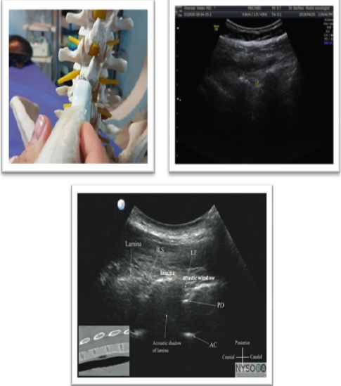
Figure 4 Effects of P sources and application rates on residual total N in soils after harvest.
Note: P sources ending with 1, 2, 3 and 4 indicates 0, 20, 40 and 60 kg P ha-1 respectively
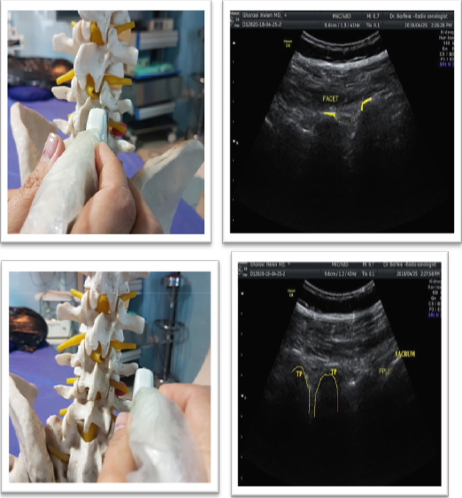
Figure 5 Effects of P sources and application rates on residual total N in soils after harvest.
Note: P sources ending with 1, 2, 3 and 4 indicates 0, 20, 40 and 60 kg P ha-1 respectively
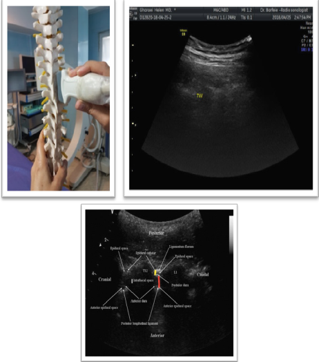
Figure 6 Effects of P sources and application rates on residual total N in soils after harvest.
Note: P sources ending with 1, 2, 3 and 4 indicates 0, 20, 40 and 60 kg P ha-1 respectively
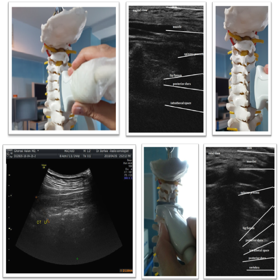
Figure 7 Effects of P sources and application rates on residual total N in soils after harvest.
Note: P sources ending with 1, 2, 3 and 4 indicates 0, 20, 40 and 60 kg P ha-1 respectively
Sagittal view & neuraxial content through the acoustic window from posterior to anterior |
Echogenicity |
Flavum ligament* |
Hyperechoic |
Epidural space |
Hypoechoic |
Posterior dura* |
Hyperechoic |
CSF# |
Anechoic |
Anterior complex” |
Hyperechoic |
Table 1
Ultrasound guided sagittal view of lumbar spine
*flavum ligament and posterior dura may be seen as one hyperechoic complex name posterior complex.
#horizontal hyperechoic pulsation of cauda equine may be seen in CSF.
“Anterior longitudinal ligament and anterior dura are near and have a one hyperechoic reflex as anterior complex.
Ultrasound guided epidural injection
Put the probe at the midline longitudinally to have a sagittal view of the hyperechoic spinous process. Move it a little farther at the paramedian line with heel in maneuver to see the space between the hyperechoic lamina as a hypoechoic acoustic window through which the neuraxial content are visible. The acoustic window between the lamina provides an easy way to spinal and epidural injections. The angle of insonation that produces the best ultrasound visualization of the neuraxial structures or the posterior complex (PC) closely mirrors the angle or trajectory for needle insertion.24−26 Epidural injection performs in prone position but it is possible at lateral or semi lateral position depends on patient comfort. Lumbar and thoracic epidural injection could perform at any level but epidural injection is safer to perform under L2 and thoracic region injection in T4-T6 is more hazardous due to less blood supply. Cervical epidural injection performs in prone position while patient head is hyperextend. It is more difficult than lumbar or thoracic region and best achieve at C7-T1 space by long -axis view of paramedian line with sagittal scanning of the acoustic window. Acoustic window is clearer near to midline, so doesn’t move probe more laterally and use hill- in maneuver and tilt the ultrasound probe slightly medially near to midline not over spinous process to see acoustic window more clearly. By viewing the acoustic window, you can easily insert the needle under the probe with in-plan technique and direct it to the window. The pop sensation in the blind method will also spark you, though in the cervical injection is not very helpful. Benefit the fluoroscopy view and confirm the correct location by injecting the contrast material for patient safety (Figure 8) (Figure 9).
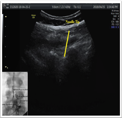
Figure 8 Effects of P sources and application rates on residual total N in soils after harvest.
Note: P sources ending with 1, 2, 3 and 4 indicates 0, 20, 40 and 60 kg P ha-1 respectively
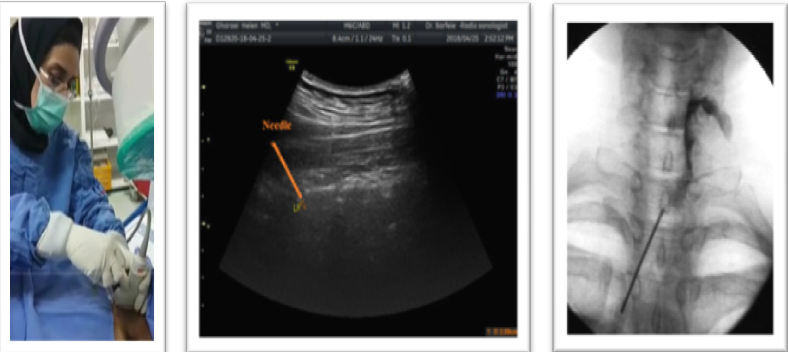
Figure 9 Effects of P sources and application rates on residual total N in soils after harvest.
Note: P sources ending with 1, 2, 3 and 4 indicates 0, 20, 40 and 60 kg P ha-1 respectively
Clinical pearl Be aware the needle passes only the yellow ligament. Sometimes PC is more prominent and hyperechoic so doesn’t mistakenly enter needle into it, consider dense superficial lamina is more parallel to LF to deeper PC.
Ultrasound guided caudal epidural injection
To do a caudal injection at the end of spinal column , place the curve prob transversly on the midline of the spine to have a short axis -view. Then push it down on the spinous process and the sacrum to see the mickymouse sign: the ears are the same as the hyperechoic sacral cornu and the middle hypoechoic space between the ears is the location of the sacral hole. It may be seen ,up and down the hole two hyperechoic thin lines that are the sacral membranes. Then place the probe longitudinally on the midline for a long-axis longitudinal view. The area of the sacral hole appears as a first hypoechoic paralell line under the dense sacral bone. Guide the needle in-plan under the probe to the hole and do not go ahead when you see the needle entry(no more than S2). Use a fluoroscopic view of diagnostic christmas tree for the patient safety (Figure 10).
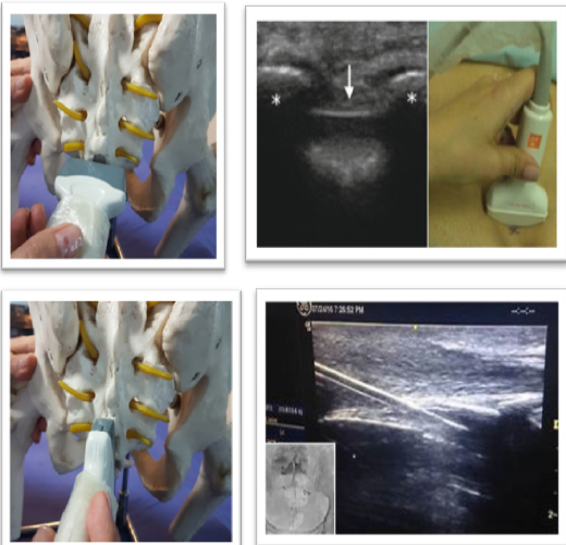
Figure 10 Effects of P sources and application rates on residual total N in soils after harvest.
Note: P sources ending with 1, 2, 3 and 4 indicates 0, 20, 40 and 60 kg P ha-1 respectively
Ultrasound guided medial branch block
After identification of the midline and paramedian view, take the probe more laterally and move away from the lamina to see the articular process that present as a continuously wavy hyperechoic line without an intervening gap. Z joint sono-anatomy view on the axial and sagittal plane is the key landmark for the medial branch block and periradicular injection. Scan the Z joint in the axial view. Then enter the needle in - plane from the outside of the probe and under it down to up (except L5 which is up to down) and toward the space between the TP and the SAP which is really their hyper echoic acoustic shadow in axial view and forward needle till contact the nearby bone. Then turn the probe 90 ° and put it longitudinally at the Z line to ensure that the needle is at the top of the transverse process and not inserted into the IVF. To maintain the patient's safety, help live fluoroscopy to ensure unwanted intravascular or epidural injection (Figure 11).
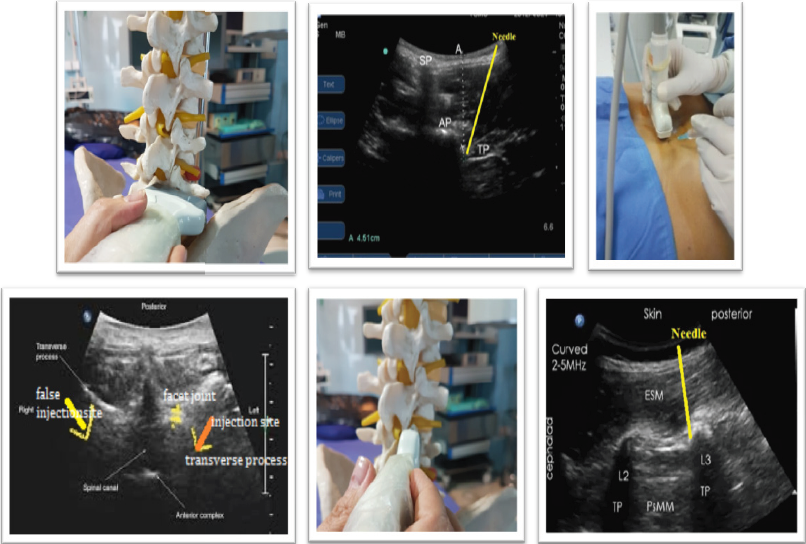
Figure 11 Effects of P sources and application rates on residual total N in soils after harvest.
Note: P sources ending with 1, 2, 3 and 4 indicates 0, 20, 40 and 60 kg P ha-1 respectively
Ultrasound guide injection at L5PPR
Injection in the L5 is performed instead of the medial branches in the posterior primary ramus (PPR) and is slightly different due to the specific anatomical location and the long blade of the iliac crest. Sometimes it is possible to perform procedure in axial view similar to upper lumbar vertebra and it need to move the probe down toward the sacrum then after viewing the last transverse process (TL5) move probe lower to see the hyperechoic line, the intersection of the S1SAP with the sacrum, insert needle with in plane approach with a sharp angle down to contact with the surrounding bone. In situation where iliac crest is high you have to perform procedure in sagittal view with out of plane oblique approach .To do this, after axial scanning of the spine and finding sono anatomic feature of Z joint put the probe longitudinally over the Z joint then guide the needle with the oblique out of plane approach in the up to down direction to reach the bony intersection of S1 SAP with sacrum (Figure 12).

Figure 12 Effects of P sources and application rates on residual total N in soils after harvest.
Note: P sources ending with 1, 2, 3 and 4 indicates 0, 20, 40 and 60 kg P ha-1 respectively
Ultrasound guided cervical MBB
Injection at the cervical region is also different due to the anatomical difference between the cervical vertebrae and the facet joint .The main point in the injection of the CMBB is to find the articular pillar in which the internal branch passes over. First put the probe transversely on the mastoid process and move it caudally to see the most superficial situated bony landmark of the upper cervical spine (TP C1). A few millimeters caudal to this structure search to find the vertebral artery by color Doppler and followed until it entered the transverse foramen of C2, where there is the C2–C3 zygapophyseal joint posteriorly. Rotate the probe about 90° to see the sagittal view of the cervical zygapophyseal joint and identify each surface simply by counting the hills (joints) and grooves (articular pillars) down. The medial branch nerves are located in the mid-distance valleys between the Z joints (C3-6).27 Insert needle in- plane under the probe toward this target point until contact the bone. Since the radicular arteries are in the immediate vicinity of the foramen and the anterior, it needs to help live fluoroscopy to confirm lack of intravascular injection (Figure 1) (Figure 13).28

Figure 13 Effects of P sources and application rates on residual total N in soils after harvest.
Note: P sources ending with 1, 2, 3 and 4 indicates 0, 20, 40 and 60 kg P ha-1 respectively
Ultrasound guided thoracic MBB
Injection of the medial branch in the thoracic region is a little different due to the presence of the ribs and its articulations with the transverse process and the vertebral body. It is preferable to put the probe transversely on the thoracic spinous process and then move it out with caution to elaborate the bony echo of the Z joint, transverse process and ribs. Since the TP is more posterior to the rib, it is clear in ultrasound and there is no overlap which makes it unclear in fluoroscopy. Incidentally, the rib helps you a lot, because it has a simple and different bony echo. Insert needle in-plane again (similar to lumbar region) to the junction of the rib with Z joint or any site on the upper border of the transverse process until touch the bone(due to different position of medial branch in thoracic region). Check the needle position in sagittal view as the lumbar region to confirm needle position on the upper border of TP and make sure it is not inserted into IVF (Figure 14).

Figure 14 Effects of P sources and application rates on residual total N in soils after harvest.
Note: P sources ending with 1, 2, 3 and 4 indicates 0, 20, 40 and 60 kg P ha-1 respectively
Periradicular injection
Transforaminal injection performs with a variety of classic, retroneural and retrodiscal techniques. In classic or sub-pedicle technique needle enter below the pedicle and above the SAP through the safe triangle zone and in retroneural technique (periradicular or selective nerve root block) needle enter lateral to the lamina and inferior to TP along the lateral border of nerve , in retrodiscal technique (kambin,s triangle) needle place lateral to the upper two-thirds of the SAP of the lower vertebra(supra-pedicular) to the lateral border of the Z joint at the medial aspect of the spinal nerve and anterior epidural space. Injection along the nerve root or periradicular injection is the safest compared to classic transforaminal injection (Figure 15).
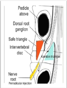
Figure 15 Effects of P sources and application rates on residual total N in soils after harvest.
Note: P sources ending with 1, 2, 3 and 4 indicates 0, 20, 40 and 60 kg P ha-1 respectively
In this injection, like the lumbar MBB, the most important point is the Z joint. Apply the probe transversally to the spinous process, move it laterally to find Z joint. It is necessary to scan SAP and IAP (as tolled before the intersection with TP & SAP and TP with VB may seem similar for the novice) (Figure 12) (Figure 14). After finding the exact location, move the probe a bit under the Z joint to see the pulse of the radicular artery(help Doppler mode), guide the needle in-plane from outside lower border of the probe down to up(L1-L4) toward artery until touch the nearby bone. For more certainty, rotate the probe 90 °in the same place longitudinally and check the needle pass intertransversalii ligament (it is visible with a high-quality ultrasound device) lower the TP in contrast to MBB which the needle is up to the TP. The only difference is in the L5 and S1nerve root injection that you need to insert the needle in plane up to down from upper border of the probe toward the target. Rule out intravascular injection with live fluoroscopy (Figure 16).
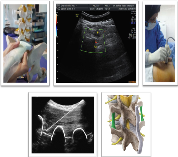
Figure 16 Effects of P sources and application rates on residual total N in soils after harvest.
Note: P sources ending with 1, 2, 3 and 4 indicates 0, 20, 40 and 60 kg P ha-1 respectively
Periradicular injection in the thoracic region is simply done by intercostals nerve block, preferably close to the midline. (32) But if you are willing to have an injection in the place the intervertebral foramen, it's easy to do with the same lumbar technique. The posterolateral approach in the cervical region helps you to use lumbar technique for cervical periradicular injection. Place the probe longitudinally on the spinous process when the patient is on prone position. Move the probe outward to pass the Z joint near to the outer border of paraspinal muscles, use heel in maneuver to see the pulse of radicular artery in IVF between Z joint. Place the needle in- plane below the long axis of the probe with a sharp angle toward the artery and nearby. Rule out intravascular injection with live fluoroscopy (Figure 17).

Figure 17 Effects of P sources and application rates on residual total N in soils after harvest.
Note: P sources ending with 1, 2, 3 and 4 indicates 0, 20, 40 and 60 kg P ha-1 respectively
Clinical pearl: Live fluoroscopy is very important because, if injected intravascularly, the contrast agent is rapidly cleared and you will not see the contrast agent afterward in the monitor.
Spinal injections have particular attention in the pain medicine. The use of ultrasound in spinal injections opens up a new eye for safe injections. Special ultrasound abilities that are constantly evolving have led to a specific position in spine intervention. It is quite natural that ultrasound will be gradually replaced by other methods. Special ultrasound abilities for spine injection, although considering its limitation, are the future of spine intervention. Therefore, simple, practical, yet safe training for ultrasound guided spine injection is necessary.
My best regards to Dr Barfei for preparing ultrasound images.
Author declares that there is no conflict of interest.

© . This is an open access article distributed under the terms of the, which permits unrestricted use, distribution, and build upon your work non-commercially.