International Journal of
eISSN: 2573-2838


Research Article Volume 4 Issue 2
Department of Biomedical Engineering, Sheikhbahaee University, Iran
Correspondence: Hamidreza Shirzadfar, Department of Biomedical Engineering, Sheikhbahaee University, Isfahan, Iran
Received: February 23, 2018 | Published: March 13, 2018
Citation: Shirzadfar H, Ghaziasgar MS, Piri Z, et al. Heart beat rate monitoring using optical sensors. Int J Biosen Bioelectron. 2018;4(2):48–54. DOI: 10.15406/ijbsbe.2018.04.00097
The heartbeat is a unit for counting the intensity of the heart function, whose unit is the beats per minute (bpm). The heart has pacemaker cells, which, by creating electrical waves, these cells cause heart rhythm from the right atrium with its spread throughout the heart, blood pumping occurs. The human heart naturally breaks about 60 to 100 bpm, which can vary with different conditions. Any disorder in heartbeat is a type of disease in the heart that can be detected by human beings by measuring beats in different ways. We present a heart rate measuring device in this paper, which first infrared light is transmitted by the infrared sensor (IR LED TX) to the fingertip and then reflects light on a Photodiode RX sensor and converted to a suitable signal by the Signal Conditioning, and suitable signal sent to the microcontroller, finally, the heart rate is measured by processing and analysis.
On the device, when the power button is pressed, the user places his fingertip on the sensors then the microcontroller key is pressed and then the heart rate is measured in 15 seconds and displayed on the LCD screen. Using this device, it can be measured easily and in a short time, heart rate with a non-invasive method without harm to the human body.
Keywords: heartbeat rate measurement, optical sensor, photoplethysmography, pulse
The heart is one of the vital organs of the body, which works by pumping blood to all organs. The heart is located inside the fibrous pericardium. The heart generally has four chambers called the atrium and ventricle, which are divided into left and right.1 The heart also has four valves called mitral, tricuspid, aorta and pulmonary the first two valves, responsible for controlling the input Blood Flow and the next two valves, control the output blood flow (Figure 1).2 The sympathetic and parasympathetic auto nerves control the function of the heart by applying change to the strength of the contractions and the heartbeat. The heartbeat has two stages of systole and diastole, which is the systole phase of the contraction and diastole phase of the heart resting phase.4 Electric impulses are produced from the sinus node and released into the heart and emit blood in the organs of the body.5 Any irregularity in the heart rhythm that affects heartbeat is called arrhythmia, which is divided into two general types of tachycardia and bradycardia. In tachycardia, the heartbeat is fast and in the bradycardia, the heartbeat is slowed down. In bradycardia, electrical messages are not properly transmitted from the atrium to the ventricle.6 Therefore, heartbeat measurement is essential for heart health awareness. Measuring heartbeat is measured in a variety of ways, such as an electric wrist, ECG devices7 and finger placement on the forearm.8 We present another method for measuring heart in this paper. The method of this device is to measure heartbeat with an optical sensor and with infrared light radiation on the fingertip and using a PIC microcontroller. This device displays the different heartbeat values in a maximum, medium, and minimum in a period of time. This device can be connected to a computer and store and analyze the obtained data. The block diagram of this device is shown in Figure 2.
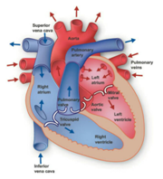
Figure 1 The heart’s anatomy.3
First, we will determine the difference between heartbeat and pulse, and then we will discuss the method and materials.
Difference between heartbeat and pulse
As previously mentioned, heartbeat is a unit for counting the intensity of cardiac function, and shows the rate of contraction and expansion of the heart, whose unit is beats per minute (bpm). The heartbeat can be measured by an electrocardiograph device. When blood passes through the heart and enters the veins, a pressure wave is applied to the veins, which causes pulses to arise in the blood vessels. In fact, the pulse is a contraction and expansion in the veins that occurs when the blood passes out of the left ventricle. The pulse can be touched and measured by placing fingers on the points where the vein passes through the bone.9 The main points for measuring pulse are radial pulse and carotid pulse which the radial pulse on the wrist and the carotid pulse on the neck.10 There is also a pulse meter device that can measure the pulse with infrared light to the earlobe. Under normal circumstances, heartbeat is similar to pulse, because pulse rate is related to heartbeat. The Figure 3 demonstrates the heartbeat and the Figure 4 shows pulse rate chart.

Figure 3 The heartbeat chart.11
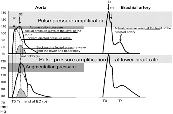
Figure 4 The pulse rate chart.12
Optical monitors
The heartbeat monitor is a smart wearable device that detects heartbeat from the body. This smart instrument uses photoplethysmography (PPG) technology and also has two sensors. The first sensor is for detecting light and another for determining motion. Its function is that the light is irradiated by the skin with a LED and then the light reflected from the body hits the detector and changes in heartbeat and body movement are measured. These optical monitors use accelerometers to detect motion. By this device can be used during activity, exercise and rest, or at any other time. The problems with these optical monitors are the presence of noise in the received signals because they have similar frequencies. Also, in some cases, measuring heartbeat is wrong, which depends on the physical body and the intensity of the user's activity.13
Component details
The microcontroller is a Component in the Electronic circuits, which consists of a CPU, RAM, ROM, and input/output ports embedded in a small chip. Microcontroller is available in a variety of devices including home appliances, automobiles, medical devices, and more which is a controller embedded in these devices. The function of the microcontroller is that it receives the signals and then responds according to the type of signal. Input and output devices associated with microcontrollers include sensors, displays, switches, and so on.14 The microcontroller can receive data with a sensor and then convert it to an electrical signal and with this signal, it performs a specific function on the device. The PIC16F628A microcontroller which is demonstrated in Figure 5 was used in this research.
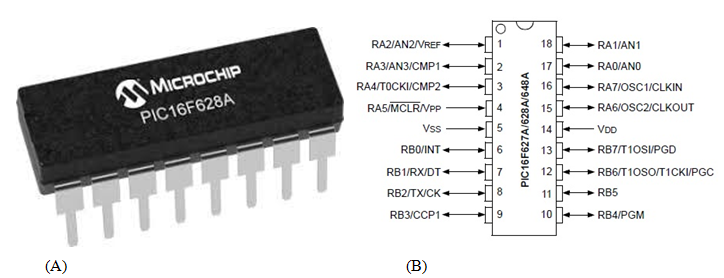
Figure 5 5A) The microchip PIC16F628A.
5B) The configuration and description of microcontroller pin.15
Operational amplifier
The operational amplifier is a variety of linear devices and a differential amplifier and one of the important parts in electronic circuits. Operational Amplifier function is to amplify DC signals and provides high gain voltage.16 This electronic piece with filtration and mathematical operators is used to amplify the signal. These amplifiers have pins for input, output and power supply. One of these inputs is inverted and the other is non-inverting. The input impedance must be infinite and in the output impedance must be zero, but in reality it is not. Because it Amplifier all kinds of operations such as collector, derivative, buffer, rectifier, etc., it is called an operational Amplifier. In this paper, the analog signal is taken from the person's body and then amplified by this operational amplifier. The Lm358 Operational Amplifier that is presented in Figure 6 was used in this project.
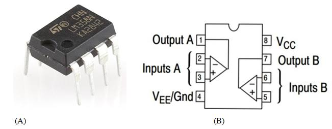
Figure 6 6A) The schematic of Lm358 operational amplifier.
6B) The configuration of pins.17
Crystal oscillator
Factors such as voltage changes, temperature, etc. affect the frequency and change it. On some circuits it is necessary that the oscillator has a Stable and constant frequency. To do this, we need to use piezoelectric crystals (Figure 7), because these crystals have a natural resonant frequency. Among the materials that have a piezoelectric effect, used more quartz because they are low-cost and Stronger than other materials.18 When the voltage is applied to this crystal, the piezoelectric effect is produced. This effect causes an electric charge to create a mechanical force by changing the shape of the crystal. In fact, this crystal oscillator can be considered as a converter for converting energy into each other. The schematic of the oscillator is an amplifier with a feedback circuit that generally behaves similar the RLC circuit.
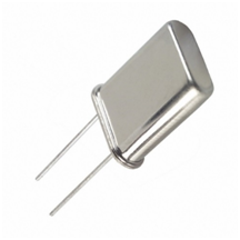
Figure 7 A miniature 4 MHz crystal.19
Sensor
In this paper, we used two of the following diode (Figure 8):

Figure 8 IR diode and photodiode.20
The infrared sensor is responsible for sending infrared light to the body. This sensor has a pair of transmitter and receiver. Using photodiode can also detect reflective light from the body and this signal is sent to the microcontroller to detect heartbeat. We used an infrared diode and photodiode here, one as the source, and the other as a detector, then we placed both of them on one side of the body. When the light is sent to the fingertip, in this case some light absorbs, some other reflects or disperses. The light reflects the volume of the blood, therefore, heartbeat is determined. When using this device, user movements need to be reduced to avoid mistakes in measurement. The reflective light that reaches the photodiode converts to a voltage using a transducer and then is filtered and amplified by the amplifier and converted to a specific and digital value with an analogue to digital converter. These values are sent to the microcontroller in the device and analyzed by it and the heartbeat is determined. Because the sensor used with reflective light determines the heart rate, therefore, it should prevent other light from entering into the environment, so that there is no mistake in measuring.21
Signal conditioning
The Signal Conditioning is to convert an output signal from the sensor into a suitable and usable quantity which will be ready for processing at a later stage. An operation such as filtering or amplify is a part of these stage.22 In this paper, we used two lower-pass filters that are similar to each other, as well as an Lm358 operating amplifier to prepare the signal. The cut-off frequency of these filters is about 2.5 Hz, which we use for these filters to avoid noise. Also, using a capacitor 1 μF, the input of the signal DC components into the device is prevented. Based on the calculations, the filter gain is obtained at around 101. Therefore, the amplifier and the filter generate a suitable signal. Then, this signal is transmitted to the PIC16F628A microcontroller. The Signal Conditioning circuit is shown in Figure 9. An infrared diode with a potentiometer is in series. This position makes it possible, when the user's fingertip is placed on two diodes that are adjacent to each other, the number that the potentiometer measure is changed. The potentiometer number changes so that the user's heartbeat is detected and the LED turns on. Then the signal is manipulated to be ready for processing in the next stages. This signal is analyzed by the microcontroller, and the heartbeat is displayed on the Seven Segment. It should be noted that at the time of the test, the user's fingertip on the sensor is fixed and does not move. To obtain the current limiting resistor with a series of infrared diode, we create a test circuit such as Figure 10 to determine its value for this type of diode.
Display unit
In this paper, the Seven Segment was used to display the heartbeat number obtained by the microcontroller. Each Seven Segment consists of seven LEDs, which with Turning on each LED, one number is displayed. Seven Segments are divided into two models, common anode and common cathode.23 Here, we are using the common anode Seven Segment which means that the anode LEDs of Seven Segment are connected to each other. Here is the pin of common anode, connected to the positive power supply. To display the heartbeat, pins of Seven Segment must be connected to the Output pins of PIC Microcontroller which, are connected to a port B with a resistor named Rs. RB0 to RB6 pins are responsible for turning on the seven LEDs of each Seven Segment. Because the numbers are multi-digit, so it's necessary to connect several Seven Segments to a port, which is called multiplexing (Figure 11). The common anode pins of each Seven Segment, with a PNP transistor and Rb resistance, are connected to the positive terminal of the power supply. Using RA0 to RA3 pins, three-digit numbers can be displayed. We used Three-Seven Segment in the main circuit of the device, because the heart rate is not at all a four-digit number therefore this Three-Seven Segment is acceptable for this measurement.
Troubleshoot
We faced some difficulties for making this device. In the following, we will discuss how to solve these problems:
Constant 5v supply: This device requires a 5-volt DC source to be able to function properly. It is not possible to use the battery due to energy loss over time. Therefore, we need to use a 9-volt adapter and also a regulator.
Transistor switching: In the electronic circuit of the device, we used two types of NPN and PNP transistors. We put the transistor in the board, but the output of the device was not correct. Then we found that the transistor pins are incorrectly positioned. Therefore, we had to examine each of the pins to identify the emitter, the base, and the collector.
Multiplexing: Due to the fact that we used several Seven Segments to display the digits, we had to connect them to the microcontroller via a multiplexing method. If this is not done accurately, the internal LEDs of the Seven Segment will not be lit correctly and false numbers are displayed.
Pulse detection: One of the most important steps in this project is Pulse Detection. The light reflected from the infrared diode must be in a certain range, that is, it should not be too large or too small. If this light is not specified in the range, the reflected light will not be properly detected. the current limiting resistor with a series of infrared diode must be calculated correctly. The point to keep in mind is that the fingertip during testing on the sensors is fixed.
We simulated the heartbeat rate device with the Proteus program (Figure 12). We create the manipulation system of the device based on the Proteus simulation and is presented in Figure 13. Based on the elements, we made the electronic circuit of the device which is shown in Figure 14. To display the value obtained from the device, we used the common anode Seven Segment that was run by the multiplexing method which displays the values with 3 digits. The infrared light can be controlled based on the RA3 pin from the microcontroller. When the button is pressed, the light is emitted from the infrared diode for 15 seconds then the heart rate is calculated on the T0CKI input (Figure 15). The electronic circuit of this device is such that, a constant and stable frequency must be applied to the microcontroller. So we used a piezoelectric crystal oscillator. The method of operation of this device is that, first, the fingertip should be placed on the sensor and press the button to run the microcontroller. When the microcontroller is launched, the NPN transistor is turned on. At this time, the light is emitted from the infrared diode to the fingertip and is reflected after it hits the blood inside the arteries. Reflected light hits the photodiode and is detected by it. In the next, reflective light convert to the signal and this signal is filtered with a low pass filter and amplified with an operational amplifier to get a suitable and accurate signal for processing. Using a capacitor, from DC noise is prevented. As mentioned earlier, the cut-off frequency of each of these filters is about 2.5 Hz. Based on this calculation of 2.5×60=150, the maximum heartbeat rate that can be recorded is 150 bpm. Here, the transistor is turned on by the microcontroller for 15 seconds and during this time the device battery is not used. At this point, the counted value is multiplied by 4 to get the correct heartbeat rate. The value obtained by the microcontroller is transferred to the Seven Segment and displayed there. For verification, we have compared the obtained results by our photonic device with android heart rate application the mobile and the both results are shown in Figure 16. As presented in these pictures the results are confirmed together. To use this device, the user must turn on the device and then place his finger correctly on the sensors and press the start button. Then, the heart rate is measured in 15 seconds and displayed on the Seven Segment. Here, to measure the device error, we measured the heart rate of four people using the device presented in this paper (Y1), as well as using another measuring device (Y2). According to these measurements, the error and standard deviation of the device were obtained and shown in Table 1.
Y1 (bpm) |
Y2 (bpm) |
Error rate |
Standard deviation |
98 |
100 |
0.02 |
4.1533
|
91 |
96 |
0.052 |
|
92 |
94 |
0.0212 |
|
101 |
103 |
0.0194 |
Table 1 Showing error and standard deviation of the device
The heartbeat rate is one of the vital parameters in every human's body, which by knowing it can detect heart disease and prevent more serious problems. Therefore, we present a heartbeat rate measuring device based on infrared light in this paper which can be measured at any time when needed. The main elements of this device include a low-cost microcontroller, which is the overall function of the device. The advantages of this device are low cost, easy to use, high speed, high precision and easy transportation.
None.
The author declares no conflict of interest.

©2018 Shirzadfar, et al. This is an open access article distributed under the terms of the, which permits unrestricted use, distribution, and build upon your work non-commercially.