eISSN: 2577-8242


Research Article Volume 1 Issue 2
1School of Mechanical and Mining Engineering, University of Queensland, Australia
2Department of Agro-Technology, University of Tehran, Iran
Correspondence: M Khashehchi, Department of Agro-Technology, College of Aburaihan, University of Tehran, Tehran, Iran
Received: August 02, 2017 | Published: October 6, 2017
Citation: Abdi A, Khashehchi M, Hooman K. Investigation of coherence behind a single foamed tube. Fluid Mech Res Int . 2017;1(2):45-54. DOI: 10.15406/fmrij.2017.01.00007
In this paper the flow structures downstream of a foamed tube are compared to those of a bare tube with the same frontal areaand length. Experiments were conducted in a wind tunnel at Reynolds numbers 4000 and 16000. Particle image velocimetry (PIV) was used to obtain velocity vector field in two different perpendicular planes. To measure the effect of flow three-dimensionality, field of divergence on both planes was obtained and compared with each other. Moreover, to characterize the size of the flow structures downstream of the tube, for each of the aforementioned cases, two-point correlation functions were used as the statistical analysis tool. Analysis showed that, compared to the bare tube, the foamed one, in the X-Z plane (stream-wise, span-wise) increases the three-dimensionality of the flow which is set forward in the perpendicular plane despite being less pronounced. Moreover, the structures downstream of a foamed tube are elongated in the stream-wise direction and are linearly independent of the inlet velocity, however, in span-wise and normal direction no significant change in the size of the structures between bare and foamed tube has been observed.
Keywords: metal foam, two point correlations, particle image velocimetry
Amongst the wide range of metal foam applications, the heat exchange industry is the most notable. Heat exchangers are devices that transfer heat from one medium to another that in most cases the two media are air and water. Specifically, air-cooled heat exchangers consist of a number of water tubes to transfer the heat between the pumped air and the flowing water through the tubes. Covering the tubes with conventional fins is one way to increase the contact area so that it can improve the thermal performance of a bare tube bundle, however because of the blockage and the tubes’ wake, it raises the pressure drop. Therefore, designing and optimizing finned tube heat exchangers have been widely studied to increase the heat transfer and, at the same time, reduce the air side pressure drop.1‒9
Ithas been suggested to wrap the heat exchangertubes with aluminum foam instead of fin which has a positive effect on increasing the thermal efficiency due to its larger heat transfer area surface.10‒13 Bhattacharyya et al.,10 studied different Reynolds number, Grash of number, permeability and thermal conductivity of the metal foam. Their results show that a thin foam layer of high thermal conductivity increases the rate of heat transfer. Dukhan et al.,11 showed that increasing the Reynolds number will increase the heat transfer up to a certain limit. Mahjoob et al.,12 studied the micro structural metal foam properties, such as porosity on the heat exchanger performance. They also found that the performance increases when tubes are covered by metal foam. Leong Jin’s13 results indicate that higher heat transfer rates can be obtained in metal foams subjected to the oscillating flow.
Latterly, studies regarding the flow field around the foamed tubes and its associated pressure drop are being done by researchers.14‒20 Odabaee et al.,14 conducted a numerical study and changed the thickness of foam layer to obtain an optimum thickness beyond which the heat transfer doesn’t change and the pressure drop keeps increasing. Comparing their results to those of the finned tubes shows that the total efficiency of the foam is much higher than that of the fin. Ashtiani et al.,16 reported that covering a tube with foam, increases the wake size of the tube16,17 while Khashehchi et al.,18 claimed that the wake of a finned tube is smaller than that of a bare one with the same inner tube diameter but dissimilar frontal areas. Ashtiani et al.,19 reported that adding foam to a bare tube decreases the vortex shedding frequency and increasing the surface temperature, strengthens this effect. Moreover, heating the foamed tube makes an asymmetric wake downstream of the tube where its lower part is further extended than the upper part. Additionally, Sauret et al.,20 performed an experimental and numerical study on blocks of aluminum foam with different thicknesses they observed two separation regions before and after the porous block and a non-uniform interface velocity along the stream-wise direction. Despite all these studies, many unsolved problems, like three-dimensionality of the flow, size of the coherent structures, porosity effects on the structures and etc., still need to be investigated to give us a better understanding of the effect of foams as replacements for fins on the flow filed downstream of the tube. Further, it is noteworthy to mention that, studying these problems both increases the performance of devices that are used in the energy sector, specifically heat exchangers, and also the results of these researches can be used in interdisciplinary fields like tissue engineering, aerospace engineering and etc.
Regarding the application of foamed tubes in the heat exchangers and the flow field around them, an important question will raise. Since the size of the structures is directly linked to the wake, and as a result thepressure drop, the question onthe size of the structures remains unanswered. There exist a number of investigations on the literature about the coherent structures behind circular or finned tubes and also there are other studies investigating the three-dimensionality of structures. Ganapathisuramani et al.,21 showed how stream-wise auto-correlation can be used to measure the size of stream-wise structures. Hutchins et al.,22,23 used two-point span-wise correlation to obtain statistical information regarding the width and spacing of the coherent structures. In literature, a number of studies can be found in which two-point correlation is used to obtain the shape of the structures inside the wake region.24,25
The present study, however, analyzes the size and three-dimensionality of the structures, downstream of a bare and a foamedtube,1<x/D<3, by using PIV on two different perpendicular planes at two different Reynolds number of 4000 and 16000 based on their outer diameter and the upstream velocity (of the air to the wind tunnel).
Set-up
The experiments were performed in an open loop suction wind tunnel shown in Figure 1 with a fan rotor driven by 17kW electric motor. The air speed through the tunnel was controlled manually by a pitot tube. The flow conditioning consisted of a fine mesh screen, followed by a honeycomb section containing cardboard tubes and removable flow-smoothing screens. The contraction was three-dimensional with a 5.5:1 area ratio. The test section was0.46m wide, 0.46m high and 2.0m long with walls were made of transparent Plexiglas that allows photography of the flow field. Figures 2 & 3 illustrate the side and the top view of the test section and the setup. In both figures, the center of coordinate system is identified by a cross sign on the tube (rear stagnation point). The stream-wise, normal and span-wise directions are indicated by “X”, “Y” and “Z” axes, respectively.
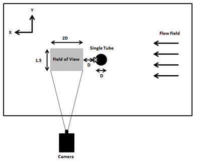
Figure 2 Side view of the experimental setup. The laser is located above the field of view on top of the wind tunnel. The cross represents the coordination center.
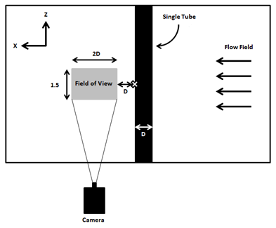
Figure 3 Top view of the experimental setup. The laser is illuminating the Field of view from the side. The cross represents the coordination center.
The velocity range of air in an air-cooled heat exchanges is generally between 1 to 4ms-1, and the diameter of the tubes could be between 6 to 60mm.26 Hence, in this experiment based on the tube outer diameter D (62mm) and the inlet velocities UInlet (1 and 4ms-1) Reynolds numbers of 4000 and 16000 were selected. The free-stream turbulence intensity in the absence of an obstacle (cylinder) is up to 0.5% for the stream-wise fluctuating velocity u and 0.75% for the transverse fluctuating velocity v.
Particle image velocimetry (PIV)
The flow was seeded with oil droplets of 1.9μm diameter generated by a Dantec seeding generator. Light source was a Dantec dual cavity flash-pumped Nd:YAG laser emitting 0.532μm radiation. Two perpendicular, intersecting planes were illuminated consecutively. Hence, to obtain converged statistics, in each continuous run, a total of 3000 images were taken. A schematic of the optical setup is shown in Figures 2 & 3.
Images were taken using Hisense Mk II camera with a resolution of 1344×1024 pixels at a rate of five frames per second. The time delay between pulses was selected to satisfy the one-quarter rule.27 Images were post-processed using Dantec Dynamic Studio ver. 3.31. To obtain the velocity vectors, the single exposed image pairs were analyzed using an adaptive correlation algorithm introduced by Soria.28 The final pass used a 32pixel square interrogation area with 50% overlap, with correlations done by three point Gaussian sub pixel interpolations. Approximately 10,000 velocity vectors were generated per image pairs in the total field of view with less than 5% of substituted vectors.
The uncertainty in the PIV velocity measurements was estimated taking into account the uncertainty in the sub pixel displacement estimator of 0.1px, and the uncertainty in the laser sheet alignment of 1%. The uncertainty relative to the maximum velocity in the velocity components at the 95% confidence level for these measurements is 0.3%. Other uncertainty sources including those due to timing, particle lag, seeding uniformity, and calibration grid accuracy were minor. In addition, due to the fact that in highly turbulent flows the error associated by the PIV itself is much smaller than the turbulence fluctuations, the uncertainty related to that error found to be less important than that of statistical sampling analysis.29 Thus in this study only statistical sampling analysis is performed to estimate the measurement uncertainty.
Tube samples
The experiments were conducted on bare and foamed tubes (Figure 4). The length of both tubes was 600mm and their outer diameter was 62mm. Moreover, the extra 60mm of the length on each side of the tube was used in order to support the tube and install it in the tunnel. Aluminum foam with 15mm thickness was wrapped around a bare tube with 32mm of diameter. This foam consists of ligaments forming a network of inter-connected cells. The sample “pores per inch” was 10 and the effective density was about 5% of a solid of the same material.
The blockage ratio of the wind tunnel was about 13% based on the outer diameter of the tube and the height of the test section. Richter’s30 studies show that for a circular tube with a blockage ratio of less than 25% blockage effect is insignificant. Hence, no correction for tunnel blockage was applied on the results of the present study. Although it is expected that increasing the blockage, amplifies all the forces and pressure coefficients,31 analysis of these forces is beyond the scope of this paper.
Figure 5 illustrates the mean stream-wise velocity normalized by the inlet velocity at both Re=4000and 16000 in the wake centerline of the circular tube. Moreover, result of Parnaudeau et al.,32 which was obtained at Re=3900, at the same location are plotted in this chart for comparison purpose. As seen, the difference between their result and those of current study at Re=4000 is insignificant. It is observed that in the bare tube case, the normalized mean stream-wise velocity in the recirculation zone increases reaching the inlet velocity. For the foam at both Reynolds numbers, however, the convergence toward the inlet velocity is happening far more gradually. Further, comparing the recirculation zone length in all cases, confirms the elongation of the mentioned length to the Reynolds number in the foamed tube similar to observations made by Ashtiani & Khashehchi et al.16,18
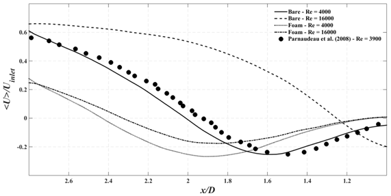
Figure 5 Comparison of the mean stream-wise velocity in the wake centerline of circular (X-Y Plane).
Figure 6 shows the variance (normal stress) of the stream-wise velocity fluctuations in the wake centerline. The normalized stream-wise normal stress in a bare cylinder starts from zero reaches two peaks and then again decreases to reach zero.33 For bare cylinder at Re=16000, the first peak is out of the field of view. For the one at Re=4000, both peaks are distinguishable; yet, considering the aspect ratio and blockage effects (aspect ratio of 20 and blockage of 4.3% for Parnaudeau, 7.5 and 13% for the present study), and the velocity variance’s being sensitive to them, the first half of the obtained data for this case is slightly different from those reported by Parnaudeau et al.32 At lower Reynolds number for the foam the same two peaks can be observed. However, for the one at the higher Reynolds number a flat peak can be noted. The peak starts 1.5D away from the tube and extends to 2.5D downstream of the tube. Interestingly, like what has been observed in Figure 5 for the foam cases, variance of the stream-wise velocity seems to be linearly independent of the Reynolds number.
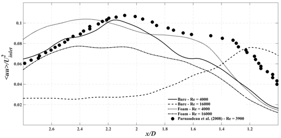
Figure 6 Comparison of the variance of the stream-wise velocity fluctuations in the wake centerline 1.0D and 2.8D away from the tube (X-Y Plane).
Covariance (Reynolds shear stress) of the stream-wise velocity fluctuations at three x-locations (x/D=1.0, x/D=1.5 and x/D=2.0) in the wake are plotted in Figures 7(A–D). Downstream of a bare cylinder, the Reynolds shear stress (<uv>) profile is expected to present two peaks near the cylinder due to the transitional condition of the shear layer. Moreover, the peaks are asymmetric about the origin. Although, velocity fluctuations between the two peaks are negligible, but by setting back from the cylinder to the end of recirculation zone, where the primary vortex is forming, these fluctuations become more disturbed. Further, in this region the size of peaks grow to reach the maximal value at the end of the recirculation zone where peaks of shear layer and primary vortex are overlapped.32
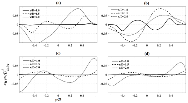
Figure 7 Comparison of the covariance of the stream-wise velocity fluctuations at three x-locations (X-Y Plane); (a) Bare tube at Re =4000, (b) Bare tube at Re =16000, (c) foam tube at Re =4000, (d) foam tube at Re =16000.
The flow field downstream of a bare tube at Re=4000, follows the same trend. Comparing the results of bare tube at Re=16000 with Re=4000 shows that in the former, the Reynolds shear stress profiles at x/D=1D and 1.5D are similar to those at x/D=1.5D and 2D in the latter. For the same case where x/D=2.0, numerical values of the peaks are considerably lower than those off the recirculation zone; as one would expect because of less pronounced fluctuations off the recirculation zone. By looking at the foam cases, however, one could observe unusual trends. Interestingly, the intersection of the plots at three locations for both cases is at y/D=-0.1, which could be due to the arrangements of the pores. The flow that discharges from the pores can have significant effect on the recirculation zone; besides, the arrangement and orientation of the pores can move the center of this zone.16‒18 Moreover, in both cases, the size and location of the peaks on both sides are almost the same at x/D=1.0 and 1.5. Nonetheless, 2D downstream the tube, the size of the peaks for Re=4000 is about two times more than the one at Re=16000; same can be observed in Figure 6 for the stream-wise normal stress. Figure 5 shows that for both cases x/D=2.0 is inside the recirculation zone and the flow has not reached the end of the zone where the maximum peak is occurred. Hence, what can affect the Reynolds shear stress in this region could be either the deflection of the shear layer due to its flapping or contribution of the flow exiting from the pores into the wake region. Interestingly, for foamed tube at higher inlet velocities the deflection of shear layer is not pronounced unlike the bare cylinder case. The effect of this deflection on the size of the peaks is not changing. Also increasing the velocity decreases the magnitude of the covariance. Therefore, at higher velocities lower peak values are expected.
As the continuity equation states, the rate of mass which enters into a system is equal to the rate at which mass exits. The general differential form of this equation for incompressible flow can be written as
(1)
This means that the divergence of the velocity field is zero everywhere. However, for two dimensional flow fields, nonzero divergence values could present three-dimensional zones where significant out-of-plane velocities are observed.
Figure 8 is a comparison between the mean divergence field of the PIV results on both X-Z and X-Y planes (mean divergence field in X-Y plane indicates the average of and in X-Z plane indicates the average of where the maximum and minimum values of all sub-figures are set to be +0.1s-1 and -0.1s-1 for comparison purposes. MATLAB “divergence” command with stream-wise and normal/span-wise velocities was used to generate the divergence filed, and then, by applying time averaging to the divergence set, the mean values were calculated. In the interest of brevity, two sub-figures regarding the mean divergence fields of bare cylinders at both Reynolds number on the X-Y plane are not shown in the paper because for both cases the fluctuations on the field are significantly small and negligible. However, for the foam cases on the same plane, by increasing the velocity, the development of negative zones are noticeable. As it has been pointed out earlier, the impact of the arrangement and orientation of the foam pores specifically inside the recirculation zone on the flow field is significant. It is noteworthy to mention that increasing the inlet velocity for the foam case decreases the magnitude of the fluctuations, seen in Figure 6, but at the same time it does cause local three-dimensionality in flow field as clearly shown in Figure 8f.
Figure 8 Comparison of the mean planar velocity field’s divergence, the maximum and minimum limit of all the figures are set to be +0.1s-1 and -0.1s-1 for comparison purpose; (a) Bare tube at Re =4000 (X-Z), (b) Bare tube at Re =16000 (X-Z), (c) foam tube at Re = 4000 (X-Z), (d) foam tube at Re = 16000 (X-Z), (e) foam tube at Re =4000 (X-Y), (f) foam tube at Re =16000 (X-Y)
Sub-figures (a), (b), (c) & (d) have been obtained on X-Z plane. This plane is expected to have positive and negative zones due to vortex shedding. In the first two sub-figures, comparison shows that for bare cylinder at the high Reynolds number, in the positive zone, where , is pushed toward the tube since the length of the recirculation zone is small compared to the bare one at low Reynolds number in which this positive region is weak and far from the tube. This comparison becomes more interesting when one compares the sub-figures (c) & (d) with (a) and (b). Likewise, for the last two sub-figures, the location of positive regions for both cases (high and low velocity) are not changing since the length of the recirculation region is almost the same for both cases where from 1D to 2D negative region and from 2D to 3D positive region exits for both cases. But increasing the inlet velocity has a major impact on both positive and negative regions and the magnitude of in the case with the higher velocity is almost twice as big as the case with lower velocity. Considering the magnitude of the peaks of the Reynolds shear stress profile (that is almost two times larger in the lower velocity case), the magnitude of normal velocity gradient (that is two times higher in the case of the higher velocity), and the effect of arrangement and orientation of the pores on the flow field inside the wake region, one can conclude that, inside the recirculation region of a foamed tube, increasing the velocity is proportional to increasing the rate of normal velocity gradient. However its effect on the fluctuations is inverse.
To investigate the size of the structures formed behind the cylinder and to identify a pattern for them in space, a statistical study is needed. Hence, the two point correlation function of the velocity was used:
(2)
where xi and xj are the coordinates in stream-wise and normal/span-wise directions. The <> indicate both spatial and time averages.
The comparison of two-point correlations of the stream-wise, normal and span-wise directions is demonstrated in Figure 9. Studying the sub-figures (a), (c) and (e) regarding the stream-wise correlation of Ruu, Rvv and Rww, shows that changing the velocity doesn’t change the magnitude of Rii in the foamed tube. However, this magnitude for the same cases starts changing for the normal and span-wise correlations by setting back from . In sub-figures (a) and (c), correlation and anti-correlation regions are clearly demonstrated by positive and negative values that indicate the vortex pairs. The size of structures for foamed tubes is about 1.5D and for the bare ones is almost 1.1D, albeit in case of bare tube at Re= 4000, this size is a bit smaller. In sub-figure (e) where stream-wise correlation of Rww is shown, it is obvious that the size of the structure for all the cases is about 0.5Dregardless of the Reynolds number. Moreover, in the same sub-figure, the correlation of the structure with the vortex pairs in the stream-wise direction is insignificant, and this anti-correlation reaches zero in . Sub-figure (b) shows the existence of vortex pairs with inverse rotation direction above and below the structure. The correlation of this structure with its pair is about 50% more than the ones in stream-wise direction (sub-figure (a)). The size of the structures in figure (b) for all the cases is about 1D which is smaller compared to the ones in figure (a). Interestingly in sub-figure (d) where Rvvcorrelation in normal direction is presented, the strong correlation of the structures all along the available field of view is obvious. This means that the structures associated with the normal velocity fluctuations in the normal direction are stretched larger than 3D for all the present cases. In this sense, the structures in the bare tube at Re= 4000 are slightly compact compared to the other cases. Sub-figure (f) has the same trend as (c) but it has no anti-correlation regions and its structures are twice as big as the ones in the stream-wise direction. In addition, the size of detached structures from the foam cases is smaller than those of the bare tubes regardless of the velocity.
Figure 9 Ruu, Rvv and Rww correlations; (a) stream-wise correlation of Ruu, (b) normal correlation of Ruu, (c) stream-wise correlation of Rvv, (d) normal correlation of Rvv, (e) stream-wise correlation of Rww, (f) span-wise correlation of Rww.
Figure 10 compares two point correlation map of the stream wise velocity fluctuations (Ruu) at Reynolds number of 4000 between bare and foam covered cylinder at X-Y plane. Similar to Figure 9a, for the foam covered cylinder a positive correlation region elongated in the stream wise is observed. The correlation map is dominated by a structure like the one shown in Figure 11a. The separated structure from the cylinder creates positive correlation in the stream wise direction. In addition, anti-correlate regions are recognizable on the sides of the dominant coherent structure for both bare and foam covered cases. It should be noted that these anti-correlations are clearly elongated for the foam covered cylinder compared to the bare one.
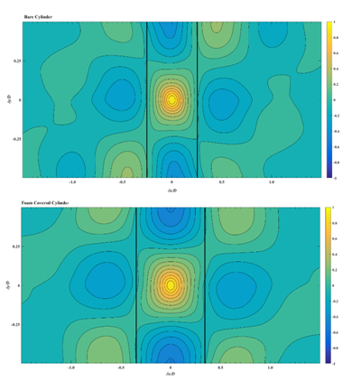
Figure 10 Comparison of two point correlation map of the stream wise velocity fluctuations (Ruu) at Reynolds of 16000 between bare and foam covered cylinder - black lines are used to show the zero correlation at center line.
Figure 11 shows a number of normalized samples of instantaneous velocity fluctuation distributions giving a rough idea of the shape and size of the structures. All these sub-figures have been normalized with the inlet velocity and for comparison purposes, their maximum and minimum limits are set to -0.5 and +0.5. These sub-figures are presenting, u/<U> of the foam tube at Re = 16000, v/<U> of the foam tube at Re = 16000, w/<U> of the foam tube at Re = 16000, w/<U> of the bare tube at Re = 16000 and v/<U> of the bare tube at Re = 4000 respectively. Sub-figure (a) depicts that, as it is mentioned earlier, for the foamed tube at the high Reynolds number, the size of structures in x-direction regarding the stream-wise fluctuations is about 1.5D. This size in y-direction for the normal velocity fluctuations covers the whole field of view as it is clear in sub-figure (b) and discussed in the previous section. Sub-figures (c) and (d) illustrate the structures of foamed and bare tube formed from the span-wise fluctuations at Re = 16000. For both cases, the size of structures is about 0.5D in x-direction. However, in z-direction, the former has the size of 1.5D and the latter is nearly 1D as expected. Finally, it is clear from the sub-figure (e) that, in the bare cylinder at the low velocity, the size of structures shaped from the normal velocity in x-direction is about one third of those in y-direction.
Figure 11 Comparison of the normalized sample instantaneous velocity fluctuation distribution, the maximum and minimum limit of all the figures are set to be +0.5 and -0.5 for comparison purpose; (a) u/<U> Foam at Re = 16000, (b) v/<U> Foam at Re = 16000, (c) w/<U> Foam at Re = 16000, (d) w/<U> Bare at Re = 16000, (e) v/<U> Bare at Re = 4000.
Figure 12 presents the mean vorticity field in X-Y plane of bare and foam covered cylinder at both Reynolds numbers. It is well established that, in a three dimensional flow, vorticity strengthens when a vortex line is stretched and in general, separated structures tend to lengthen in a turbulent flow. In this figure it is clear that the length of mean vortex is longer for foam covered cylinder and unlike the bare cylinder, in the case of the foamed one, by increasing the Reynolds number this length does not shrink. Another interesting observation is the angle of the vortex line; for bare cylinder the two vortex lines inclined toward the cylinder’s center line and the inclination increases by increasing the Reynolds number which indicates that size of structures and flow three dimensionality decrease by increasing the inlet velocity, but in case of foam covered cylinder, not only the length of the vortex lines does not change but also the change in the angle of these lines is insignificant. Hence it is possible to conclude that the size of separated structures from the foam covered cylinder is linearly independent of Reynolds number and also using foam to cover a bare cylinder would increase the magnitude of three dimensionality flow.
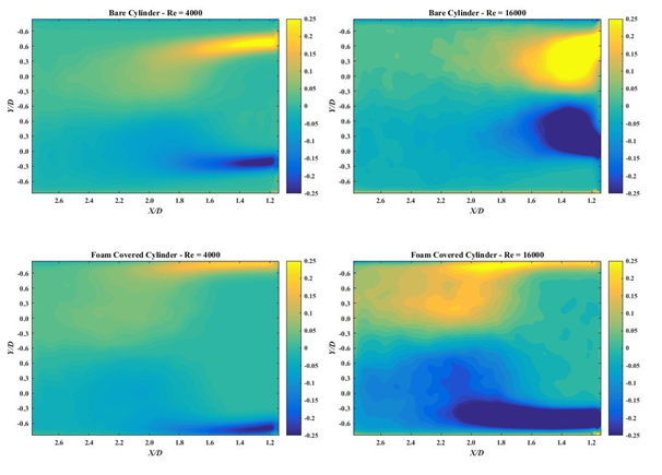
Figure 12 Mean vorticity field for bare and foam covered cylinder at Reynolds numbers of 4000 and 16000 in X-Y plane, the maximum and minimum limit of all the figures are set to be +0.25 and -0.25 for comparison purpose.
Two point correlations as a statistical tool and divergence as a mathematical tool were applied to investigate the structures behind a single foamed and bare tube. To perform this experiment, a two dimensional Planar Dantec Dynamic PIV system in the low speed wind tunnel was used. Measurements have been conducted at two different Reynolds numbers of 4000 to 16000.
Results showed that foamed tube increases three-dimensionality of the flow in the X-Z plane, however, on the X-Y plane, three-dimensionality magnitude is lower compared to the bare tube. This could be as a result of the arrangement and orientation of the foam’s pores, specifically inside the recirculation zone where increasing the inlet velocity decreases the magnitude of the fluctuations in this region. Nonetheless it causes local three-dimensionalities in the flow field in X-Y plane. Moreover, the structures downstream of a foamed tube are elongated in the stream-wise direction and are linearly independent of the Reynolds number. Further, in span-wise and normal directions the structures of bare and foamed tube are slightly similar in size.
Furthermore, this study shows that using foamed tubes as an alternative for the finned ones in heat exchangers, needs more investigations regarding the effect of heat on the flow field. Since, at the ambient temperature, the foamed tube shows irregular trends like having lower magnitude of three-dimensionality in X-Z plane compared to a bare cylinder which could not be the case for the heated foam.
None.
Author declares that there is no conflict of interest.

©2017 Abdi, et al. This is an open access article distributed under the terms of the, which permits unrestricted use, distribution, and build upon your work non-commercially.