eISSN: 2577-8242


Technical Paper Volume 2 Issue 1
Department of Mechanical Engineering, Kathmandu University, Nepal
Correspondence: Biraj Singh Thapa, Department of Mechanical Engineering, Kathmandu University, Turbine Testing Lab, Dhulikhel, Nepal
Received: December 13, 2017 | Published: January 31, 2018
Citation: Chhetry B, Thapa B, Thapa BS, Koirala R (2018) Design Optimization of Head Cover of Vertical Francis Turbine from Maintenance Perspective in Context to Sediment Laden River Projects. Fluid Mech Res Int 2(1): 00016. DOI: 10.15406/fmrij.2018.02.00016
Francis turbine operating in sediment laden river projects, excessive wear and damage often occurs on the guide vanes, facing plates, runner and labyrinth rings due to sand erosion. The requirement of dismantling the head cover to repair the facing plates and wearing ring is one of the major influencing parameter of turbine assembly design to increase down time during turbine maintenance. This article discusses on standard assembly design of head cover for vertical Francis turbine installed in Nepalese hydropower station, including its effect on unit outage during overhauling of the machine. Design optimization of head cover has been carried out by considering the maintenance performance analysis tool, intending to explore the ease of maintenance and to identify the maintenance friendly assembly design of vertical Francis turbine.
Keywords: sand erosion, francis turbine, head cover, facing plate, assembly design, turbine overhauling
Hydropower machinery has long service life when designed with well adaptation to the operating conditions and expected maintenance demand. Operating conditions of the hydraulic machine are required to be monitored and recorded, as it contains the information of causes of failures and faults, helps to determine the performance of the plant.1 The cost associated with maintenance work has significant effect on total operational costs of the hydropower plant. The reliability of system operation and production cost in an electric power system is highly affected by the maintenance outage of generating facilities.2
Experience of running hydropower station reveals that even after detailed project planning and stage wise measures on quality control from inception to commissioning, several unforeseen problems do occur. Most of them occur during the operation and maintenance resulting in forced outages/low generation and load shedding etc., causing misery to the consumers and undesired set back to the overall economy.3 Sediment–induced turbine wear in hydraulic machinery is probably the most serious problem in operation and maintenance of hydropower projects in Himalayan region.4
The available machinery at existing hydro stations has been adversely affected by high sedimentation in Nepalese rivers. The underwater components such as guide vanes, runner, facing plate and wearing ring are most affected in run off river projects causing forced outage.5 Studies have shown that up to 80% of hydro turbines required for future installations under Himalayan basin in Nepal will need Francis type of turbine.6 Most of Francis turbine installed in Nepalese hydropower stations need frequent overhauling for maintenance and repair of eroded parts.7
Down time of machine during the major maintenance such as turbine overhauls, determined by the easiness of disassembly and assembly of turbine parts.8 The down time during turbine overhauling work not only depend upon the state of underwater components and repair methodology.
It is of great importance that the assembly design of turbines is made for easy disassembly and assembly of component to reduce downtime. The assembly design determines the maintenance approach for repair of damaged underwater components during turbine overhauls.
Disassembly of Francis turbine includes components removal process as per the existing maintenance approach such as downwards removal and upwards removal procedure. The upward maintenance approach, for removal of turbine components is either possible from turbine pit or rotor end, depends on turbine assembly design. A widely used method is to dismantle the main parts such as runner and guide vanes from downward and then lift them up to erection bay with help of power house crane.
Several studies have been made to investigate the problem of silt erosion in hydraulic turbines and analysis for design optimization of Francis turbine for sediment laden river.9‒12 The studies mainly focus on effect of sand erosion on runner and guide vanes of the Francis turbine and its optimization for sediment operating river projects. Besides the runner and guide vanes, other turbine components such as facing plates and wearing rings are found severely damaged because of erosion, and need timely repair to increase the turbine performance.
Author has made some case studies on vertical Francis turbine of Nepalese hydro power stations to observe the performance of turbine and identify the influencing parameters of assembly design from maintenance perspective.13,14 The study has shown that, disassembly and assembly of the head cover to repair- replace facing plates and wearing ring is one of the major influencing parameter that increase the outage time during turbine overhauls.
Assembly or disassembly for downward approach requires a comparatively large opening below spiral case which is difficult to achieve with low head turbine with large dimension. Hydropower stations of run-of-river type scheme with medium head projects in Nepal, such as Marsyangdi Hydropower station, Middle Marsyangdi Hydro Power Station15 and Kaligandaki A Hydropower station16 are preferred downward approach to repair the runner and guide vanes. Modi Khola with low head run-of-river type hydro power projects in Nepal adopts the upward maintenance approach for repair and replacement of underwater turbine components.17 In any case, dismantling of head cover is required to repair and replacement of facing plate through upward maintenance approach.
The paper put forward the modifications on head cover design to ease the assembly design of vertical Francis turbine from maintenance perspective. The down time during turbine overhauling for turbine assembly with modified head cover designs are computed through event sequence analysis. The optimized head cover design is established by adopting the turbine performance tool with respect to the reference case design, such as to minimum unit outage hour occur during turbine overhauling.18
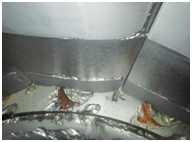
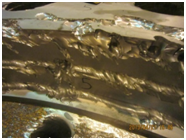
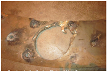
Turbine assembly of Kaligandaki A Hydro power station has been considered as reference case design. The detail analysis of suspended sediment load passing through the turbine and its effect on turbine components of reference case has been made by same author.14 The severe sand erosion has been observed on runner, guide vanes, facing plates and wearing rings due to high sediment load passing to turbine every year. Figure 1 shows damaged photographs of facing plates and wearing ring during turbine overhauling works of reference case.
(a) (b) (c)
Figure 1 Photos of sand erosion in head cover assembly components at Kaligandaki “A” HEP after one year of operation: (a) Damages of guide vanes, facing plate and wearing ring of head cover. (b) Damage of wearing ring and (c) Damages in facing plate.18
The turbine assembly design has facilities to dismantle the turbine parts from downwards as well as from turbine pit. The first approach facilitates the removal runner from downwards through a recess below the spiral case foundation whereas the latter allows the removal of turbine parts from upward through an access of turbine pit. The combined maintenance approaches have been in practice for disassembly and assembly of turbine components during machine overhauls. The Figure 2 shows the sectional view of turbine and head cover assembly of reference case.
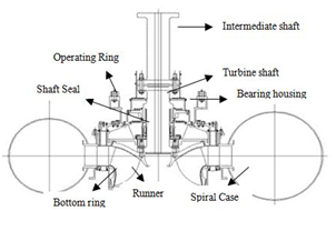
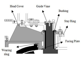
a. Cross section of Turbine Assembly b. Cross section of head cover assembly
Figure 2 Detail of component assembly of reference case.
The disassembly work during overhauls, removal of intermediate shaft, guide vane operating mechanism, head cover and turbine shaft including turbine bearing housing and shaft seal assemblies are taken out from upward approach through turbine pit. Whereas, the bottom rings, guide vanes and runner are taken out from downward approach. Removal of turbine guide bearing, shaft seal assembly, operating ring including intermediate shaft are required prior to head cover disassembly.
The replacement works during overhauls, dismantling of facing plates and wearing rings from head cover require removal of several flat head bolts fasten between cover and plate. Removal of flat head bolts from plates and rings require welding a spare bolt on head of existing bolt at facing plates and remove out the plate with the help of wrench and hydraulic jack. This sequence applies to remove out hundred bolts attached to facing plate with cover.
Similarly, fasten of bolts to the facing plate requires tightening of flat head bolts , removing the burrs from head of bolts by chiseling, inserting the dowel pin to fix the bolt and facing plate and finishing by surface grinding process. The Figure 3 shows the sequence of fixing flat head bolts on facing plate.
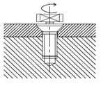
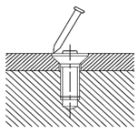
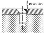
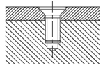
Figure 3 Assembly sequence of flat head bolt on facing plate.
It is observed that effect of sand erosion has found on the area of flat head bolt on facing plate. It may be due to unmatched bolt head on facing plate and improper surface finishing during assembly of bolts. It is difficult to achieve the precise surface finish on this area. It has also practiced to apply HVOF coating on surface of facing plate to protect the plate from sand erosion. The flat head bolts have not been considered for coating as it may require special arrangement to achieve the required coating thickness on periphery of bolt head surface. The uncoated area may have tendency to erode faster than coated area due to sand erosion.
The difference of surface level between flat head bolt and facing plate surface due to the thickness of coating may be another reason that favors sand erosion. Figure 4 presents photos of initial effect of sand erosion on facing plate of reference case design. Figure 4a shows the fasten area of flat head bolts on facing plate during the replacing work of turbine overhauls. Figure 4b shows the effect of sand erosion starting on the same area of bolting after operation of one flood season.
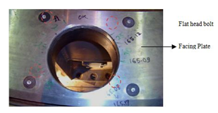
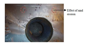
Figure 4 Observation of effect of sand erosion on bolting area of facing plate.
The details of method used for identifying the influencing parameters of assembly design and results for the reference case has been presented in earlier works by the same author Chhetry B.14 In that work, efforts are made to study the control points on reference case assembly design. A method has been developed to identify the influencing parameters of reference case. Figure 5 shows the flow chart of method analysis to establish the assembly control points followed.
The study14 has shown the requirement of dismantling head cover to replace facing plate and wearing ring is most critical assembly control point of turbine assembly design for reference case. It has been observed that design constrain of head cover has cascade effect on performance time of disassembly and assembly of components during turbine overhauls.
The head cover is designed to be stiff in order to keep the deflections caused by the water pressure. It is dimensioned for small deformation, for optimum labyrinth seal clearance and stress is normally low.19 They are normally made by fine grain carbon steel with low carbon content.
The facings adjacent to the guide vanes are normally lined with wear resistant stainless steel. This plate or liner is attached to head cover either with screw or clad welding. Labyrinth ring or seal ring is attached with head cover designed to minimize the leakage between the runner and the cover. Facing plate attached to head cover is one of the highly erosion effected area due to high velocity, cross and leakage flow, horse shoe vortex erosion around facing plate.
Due to wearing on these parts, the side gaps of facing plates and guide vanes become more than the design value, hence loss of hydraulic efficiency. Modification on head cover design is necessary to mitigate the effect of sand erosion on facing plate and ease to turbine assembly design from maintenance perspective.
Optimization of head cover can reduce the dependency of the component during disassembly, repair and assembly work. This will ease provision for replacement of facing plate, reduce the down time of the machine, and contribute to minimize the sand erosion effect, hence increase the turbine performance during maintenance.
Design optimization of head cover is carried out for selecting the best possible turbine assembly design of vertical Francis turbine in context of sediment laden river projects. In this study, two design modifications of head cover have been considered and analyze its effect on turbine assembly design from maintenance perspective.
The design modification-1 is performed to replace the damaged facing plate with new ones without dismantling the head cover so as to eliminate the disassembly event of head cover during turbine overhauling. Removal and fixing the flat head bolts for replacement of facing plate has significant effect on outage time, hence provision of stud bolts for facing plate is considered it. Figure 5 shows details of assembly design of modified head cover.
Figure 6a shows the isometric view of head cover design modification 1. The space has been generated between guide bushing plate and lower plate of head cover as shown in Figure 6b. A through- hole is made to insert a stud bolt and screw it with facing plate as presented in Figure 6c. This modification has provision to remove the stud bolts of facing plates from turbine pit.
The facing plate can be taken out from the downwards at the opening side of draft tube cone, hence requirement of dismantling head cover is eliminated from event sequence analysis. The modified design significantly reduces the outage time of disassembly and assembly of head cover during turbine overhauling. It also contributes to minimize the work of dismantling and fixing the bolts to facing plate.
The design modification-2 is considered clad welded steel liner on head cover as an alternate option of facing plate. Weld cladding is an excellent way to impart properties to the surface of a substrate that are not available from that of a base metal, or to conserve expensive or difficult-to obtain material by using only a relatively thin surface layer on a less expansive or abundant base material.20 The design eliminates event of disassembly and assembly of facing plate for replacement. It only considers the repair of liner during course of turbine overhauling. The repair of liner can be possible without dismantling the head cover, depends on damage condition of the liner due to sand erosion.
The head cover dismantling may be required to repair the liner, if effect of sand erosion is severe on the liner. Turbine assembly design with modification 2 is considered the event for dismantling the head cover to compute the standard performance time, as high sediment load has been observed in reference case. The modification has provision to split the cover into two halves from joint flange, as shown in Figure 7a. Splits are bolted transversely to the flange with stud bolting, as shown in Figure 7b. The provision has made for loosen the stud bolts of head cover from the turbine pit can be taken out from the downward approach. Figure 7c shows the cross section of head cover with clad welded steel liner.
Each modification has followed the method analysis as presented in Figure 5, and analyzed through performance analysis tool and sequence analysis method, with respect to standard performance time of reference case. Four courses of actions, preliminary work preparation, disassembly, repair- replacement and assembly work, has been considered for work measurement during turbine overhauling.
Preliminary work preparation has no effect on outage time, as this course of action falls in planning stage, hence not considered it to compute the standard performance time. Detail event sequence analysis for each course of action is carried out for both design modification on reference case turbine assembly design, and computed the standard performance time, shown in Table 1. Table 1(i) & (ii) shows the total outage of turbine assembly design with design modification 1 & 2. The standard performance time of component even for each course of action during turbine overhauling are computed with reference of case design. The standard performance time other than component event of head cover and facing plate assembly for modified assembly design are considered as in reference case design. It can be observed that design modification effect the event sequence on disassembly, repair and assembly work and reduced the performance time, hence minimize the outage time during turbine overhauling.
Course of action |
Event |
Standard performance time(hr) |
Outage time(hr) |
Disassembly of Turbine. Components |
Preliminary works |
8 |
84 |
Removal of Draft tube cone |
14 |
||
Removal of Bottom ring |
10 |
||
Removal of Gen. Oil reservoir |
10 |
||
Disassembly of guide vane assembly |
20 |
||
Removal of Turbine Guide Bearing |
6 |
||
Removal of shaft seal |
4 |
||
Removal of Runner |
12 |
||
Repair and Replacement Work |
Replacement of facing plates and wearing ring from Head Covers |
6 |
59 |
Setting of facing plates and wearing ring on Head Covers |
8 |
||
Replacement of facing plates and wearing ring from Bottom Covers |
14 |
||
Setting of facing plates and wearing ring on Bottom Covers |
12 |
||
Preparation of Assembly works |
19 |
||
Assembly of Turbine Components |
Assembly of Bottom Ring |
10 |
82 |
Assembly of guide vanes |
8 |
||
Assembly of runner |
8 |
||
Assembly of shaft seal |
4 |
||
Assembly of guide bearing |
6 |
||
Assembly of guide vane mechanism |
20 |
||
Assembly of Gen lower Bearing |
6 |
||
Assembly of draft tube cone |
8 |
||
Shaft Alignment |
6 |
||
Unit fill and final inspection |
6 |
||
Total Unit Outage Hour |
225 |
||
Table 1(i) Outage time for design medications
Course of action |
Event |
Standard performance time(hr) |
Outage time(hr) |
Disassembly of Turbine. Components |
Preliminary works |
8 |
88 |
Removal of Draft tube cone |
14 |
||
Removal of Bottom ring |
10 |
||
Removal of Gen Oil reservoir |
10 |
||
Disassembly of guide vane and accessories |
20 |
||
Removal of Turbine Guide Bearing |
6 |
||
Removal of shaft seal |
4 |
||
Removal of Runner |
12 |
||
Removal of head cover |
4 |
||
Repair and Replacement Work |
Repair of facing plates and replacement of wearing ring from Head Covers |
10 |
55 |
Replacement of facing plates and wearing ring from Bottom Covers |
14 |
||
Setting of facing plates and wearing ring on Bottom Covers |
12 |
||
Preparation of Assembly works |
19 |
||
Assembly of Turbine Components |
Assembly of Bottom Ring |
10 |
84 |
Assembly of guide vanes |
8 |
||
Assembly of runner |
8 |
||
Assembly of head cover |
6 |
||
Assembly of shaft seal |
4 |
||
Assembly of guide bearing |
4 |
||
Assembly of guide vane mechanism |
20 |
||
Assembly of Gen lower Bearing |
6 |
||
Assembly of draft tube cone |
8 |
||
Shaft Alignment |
6 |
||
Unit fill and final inspection |
4 |
||
Total Unit Outage Hour |
|
227 |
|
Table 1(ii) Outage time for Design modification 2
Modified turbine assembly design is compared with the reference case design to analyze the down time of the machine for each course of action. The comparison of outage time for turbine assembly design during overhauling works and presented in Figure 8.
Three hundred and twenty-seven outage hours has been computed to carry out the turbine overhauling works for reference case design whereas two hundred twenty five and two hundred twenty seven outage hours are estimated for design modification 1 and 2 respectively. Design modification 1 contributes 37.33%, 26.22% and 36.44 % of standard performance time for disassembly, replacement and assembly work respectively. Similarly, design modification 2 contributes 38.76%, 24.22% and 37.00 % of standard performance time for disassembly, replacement and assembly work respectively.
Head Covers are structural members applied on Francis turbine for structural rigidity, which don’t have absolute hydraulic functions. This component bears axial forces resulted from flow at facing plates and runner. Hydraulic behavior limits flow channel geometry hence, to ensure structural rigidity of turbine its structural analysis is essential. Modified design of head covers are computed for structural safety through Finite Element Method in ANSYS Mechanical based on following method:
Design |
Element Size |
|
|
Reference |
1,366,680 |
||
Modification 01 |
1,320,213 |
||
Modification 02 |
820,252 |
Table 2 Mesh information and material composition
In contrast to the reference design, von-mises stress of both modified design 1 and 2 are in allowable range as defined in Equation 1 and computed in Figure 9. Design modification 1 has largest value of maximum stress, 32.91MPa, as a section of metal has been removed from the region underneath plane of guide vane flange bushing. The region of maximum stress is scattered as shown in Figure 9. Design modification 2 has smallest value of maximum stress, 13.06MPa, as they have been externally in forced through flange bolting. In all of the cases maximum stress is around fixed point of head cover bolting to stay ring.
The maximum and minimum observed stress is in design modified 1 and 2 are 32.91MPa and 13.06MPa respectively, whereas reference case has 18.205MPa. Modification 1 and Modification 2 has slightly over scattered maximum stress limit distributed unevenly over the region. Modification 1 has an internal reinforcement at material removed part, which may have caused this distribution but since the range of variation is within the limit and the condition is in stationary component, it will not have significant effect on operation life of head cover. Regarding Modification 2 the variation in distribution pattern is an added effect of split condition, where the stress has been transferred radially and circumferentially.
(1)
For allowable deformation limit, a terminology; angle of deflection is used as expressed in Figure 10 and defined by equation 2.22 As a rule, value of angle of deflection should be less than 8x10⁻⁴ C for low head Francis and 5x10⁻⁴ C for high head Francis turbine.23 The empirical range was defined based on the experience, observation and experiments.
(2)
Since the value of
(3)
The angle of deflection can be written as;
(4)
From equation (4) the angle of deformation is calculated and is listed in Table 3.
Design |
Angle of deflection ( c ) |
Reference |
1.03 x 10⁻⁶ |
Modification 01 |
1.48 x 10⁻⁶ |
Modification 02 |
1.15 x 10⁻⁶ |
Table 3 Angle of deformation for head cover design
It can be observed from Figure 10, the maximum deflection is at the region near cover plate of turbine shaft and it is found to be gradually decreasing with increasing radius of head cover. In contrast to reference and modification 1, modification 2 has a localized region for deformation concentration at the tip of the flange. Localized concentration is generally ignored as the deflection effect is a direct function of area. The tabulated angle of deflection shows that both modification 1 and 2 are within the allowable range. Design optimization of head cover is required to ease of assembly design of vertical Francis turbine during maintenance for sediment laden river projects.24
Design of head covers having facing plate with stud bolts minimizes the effect of sand erosion and its consequences on flat head bolts of facing plate. The provision of stud bolts ease to dismantle the facing plate from head cover and aids to reduce the down time during the course of disassembly and replacement works. The design has considered the concept of replacement instead of repair on facing plate during turbine maintenance as some of Nepalese hydropower stations have been practiced to repair the facing plate during maintenance. The repair work on facing plate needs special attention to achieve the satisfactory machining performance due to limitation of plate thickness. The chances of deformation on plate are one of the risk parameter for repair work, which will have major impact on turbine performance.
Design of head covers with steel liner also minimizes effect of the sand erosion as it does not consider the facing plate. The design has considered the concept of repair the liner instead of replacement the facing plate. The design will have ease to repair as steel liner integrally bonded to facing of head cover. The repair of liner can be done at site without dismantling the head cover as per damaged condition of the liner. The head cover has also provision to dismantle from downward approach to repair the severe damage on liner due to sand erosion.
The turbine assembly design with design modifications on head cover does not require dismantling of intermediate shaft and its accessories as in reference case design. It also eliminates the requirement for removal of generator assemblies to repair and maintenance of turbine components for low head vertical Francis turbine.
It can be observed from the study, outage time of assembly design with head cover modification for stud bolts on facing plate is reduced to 32.43% than reference case, whereas 31.8% is reduced for weld cladded steel liner head cover, during turbine overhauls. Head cover design modifications make significant contribution to minimize the standard performance time of disassembly and assembly work during machine overhauling, hence reduce the outage time of the machine. Turbine assembly design with split type steel liner head cover can be implemented in vertical Francis turbine operating for low and medium sediment load , whereas, stud bolts with facing plate can be used for high sediment load river project to minimize the down time of machine during turbine maintenance.
None.
Author declares that there is no conflict of interest.

©2018 Chhetry, et al. This is an open access article distributed under the terms of the, which permits unrestricted use, distribution, and build upon your work non-commercially.