eISSN: 2577-8242


Research Article Volume 2 Issue 2
Mechanical, Industrial and Manufacturing Engineering, The University of Toledo, USA
Correspondence: Qiuying Zhao, Assistant Professor, The University of Toledo, 2801 W Bancroft St. Toledo, OH 43606, Tel 4195303239
Received: April 19, 2018 | Published: May 23, 2018
Citation: Zhao Q, Khalifin YA, Li X, et al. Comparative study of yaw and nacelle tilt control strategies for a two-bladed downwind wind turbine. Fluid Mech Res Int. 2018;2(2):85-97. DOI: 10.15406/fmrij.2018.02.00024
The structural dynamics and response of a two-bladed downwind wind turbine configuration using a tilt control concept is examined based on Computational Structural Dynamics (CSD) analysis. Nacelle tilt angles of 5, 20, 35, 50 and 65 degrees are investigated based on varying wind speeds in order to achieve the same rated power output. Yaw angles of 20, 30, 40, 50 and 60 degrees are examined with the purpose of comparing structural loads and displacements between two control methods. The computed load effects reveal that the tower top and base shear forces are reduced significantly using the nacelle tilt control compared with the yaw control method. The shear forces and bending moments at the blade root also show favorable outcomes at most nacelle tilt angles except for 65 degrees.
Keywords: Wind Turbine, Offshore, Tilt Control, Yaw Control, Simulation, Dynamics
Over the past decades there has been a sub-national increase in the usage and extraction of wind energy. Today, wind energy is the fastest growing source of electricity in the world.1 According to the World Wind Energy Association, the average growth rate of installed capacity around the world over the last decade has been 27.7%.2 The desire for improved cost effectiveness of wind power plants has motivated growth in wind turbines’ size and rated power, thus increasing the structural load that wind turbines have to endure. However, the construction and maintenance of large wind turbines is very costly. Sieros et al.3 studied the theoretical indications of up scaling to such sizes on the weight and loads of the wind turbines and showed that it will cause unfavorable increases in weight and load. Despite the amazing growth in the installed capacity of wind turbines in recent years, engineering and science challenges still exist.4 To reduce the cost of energy of wind turbines and to make them competitive to conventional power plants is one of the main goals in wind turbine optimization.
Wind turbines are designed to extract kinetic energy from the wind, usually to drive an electric generator. Almost all of the commercial wind turbines today are horizontal axis wind turbines (HAWT), meaning that the axis of rotation of the turbine rotor is horizontal. Two variations of this kind of wind turbine orientations are the upwind and downwind configurations. Downwind wind turbines do not typically need a yaw control mechanism if the rotor and nacelle have a suitable design to make the nacelle passively align with the wind. A significant advantage of the downwind wind turbine is that the rotor blades can be more flexible, decreasing the weight of the whole rotor. In addition, the blades may bend at high wind speeds and reduce the load passed to the tower. Comparing to the conventional three-bladed HAWT, the two-bladed design is relatively easy to transport and may not require on-site assembly, thus lowering the cost of energy. On the other hand, the disadvantage of the downwind wind turbine is the tower wake effect. The pressure fluctuations on the turbine as the rotor passes through the tower shadow may cause a higher fatigue load on the turbine, which is one of the main causes for the wind turbine damage.
There are different sources of fatigue loads in a wind turbine such as, pressure fluctuations on the turbine as the rotor passes through the tower shadow, trying to have stable power generations under various weather conditions, or the high variations in displacement and effective bending moments on the blade. These phenomena can happen at different locations on the blade and the tower, such as local buckling, adhesive failure and bolted joint failure.5 There should be a complete identification from the dynamics behavior of the wind turbine to avoid it. This understanding can be valuable in approximating the energetic performance as well as assessing the structural and fatigue damage of the wind turbine. In additional to calculating the fatigue loads on the wind turbine, numerous testing methods must be used to alleviate the wind turbine fatigue loads. Advanced controllers can help achieve the overall goal of decreasing the cost of wind energy by increasing the efficiency, and thus the energy capture, or by reducing structural loading and increasing the lifetime of components and turbine structures.4
The control of wind turbines is a complex problem and spans multiple fields of research, including materials, aerodynamics and power systems. As the turbine structures become larger, their components become more expensive. Wind turbine manufacturers may attempt to counteract the increase in costs by using lighter weight components that can be more flexible.6 These large, expensive and flexible components can be more susceptible to failure from fatigue and extreme loads that arise from the turbulent nature of the wind. Control system optimization to prevent extreme loads and to reduce premature fatigue load cycles becomes important to avoid component failure. The yaw system, which is responsible to rotating the nacelle around the tower axis, can contribute to increasing the energy capture through pointing the rotor swept area steadily towards the incoming wind direction. Jeong et al.7 investigated the impact of yaw error on aeroelastic characteristics of a horizontal axis wind turbine blade. Kim et al.8 showed 131 related patents to the yaw systems and discussed that the highest number of these patents refer to load reduction design and methods. He reported that the yaw system is the second most common mechanical component that contributes to an overall failure rate. Stubkier et al.9 introduced a hydraulic soft yaw system to reduce loads in the wind turbine structure without compromising the energy production of the turbine. He concluded that over the past 20 years, there has not been any significant development in the yaw system configurations.9
In this study, a new wind turbine control strategy is introduced by tilting the nacelle angle to control the power output. The concept here is that as the wind speed increases, the nacelle tilt angle is increased to reduce the blade effective pitch angle, which serves the purpose of reducing the blade loading and thus the power produced by the machine at high wind speeds. Moreover, reduction of structure loads by letting the nacelle passively rotate to compensate yaw moments from aerodynamic loads. This leads to potential lower design loads for the yaw system and other wind turbine components. In addition, a better reliability of the wind turbine can also be achieved through of the tilt control of the nacelle, which increases the general availability of a wind turbine and thus the power output. Moreover, this control method may cause lower fatigue loads on the turbine. Bottasso et al.10 studied the use of individual blade pitch control as a way to reduce the ultimate loads. Narayana et al.11 investigated the gyroscopic effect of small scale tilt up wind turbines and concluded that to avoid the cyclic motion under turbulent conditions, something like shock absorber must control the rate of changing the degree of tilting. Cui et al.12 compared some passive control systems for small horizontal axis wind turbines and concluded that the small wind turbines with a tilting hinged tail are more efficient regulator ability. However, introducing the tilt control mechanism may potentially increase the unsteady loading to the rotor blades and the tower, as the rotor behaves like a helicopter in forward flight at high tilt angles. The purpose of the present study is to assess this new tilt control method by comparing it with the conventional yaw control method in terms of the load effects on the structures of the wind turbine. Numerical investigations of a model wind turbine using the National Renewable Energy Laboratory 5MW reference wind turbine is carried out for a downwind two-bladed configuration in order to assess its aeromechanical performance and structural response for offshore wind turbine applications. This study mainly focuses on the structural dynamics of two-bladed downwind wind turbines. Computational Structural Dynamics (CSD) solver DYMORE13 is used to study the aerodynamic and structural performance on the rotor, the tower and the impact of wind turbine wakes.
The Computational Structural Dynamics code is called DYMORE-2, which is a finite element based multibody dynamics code for the comprehensive modeling of flexible multibody systems.13 Multibody systems are characterized by two distinguishing features: system components undergo finite relative rotations and these components are connected by mechanical joints that impose restrictions on their relative motion. Finite rotations introduce geometric nonlinearities; hence, multibody systems are inherently nonlinear. Mechanical joints result in algebraic constraints leading to a set of governing equations that combines differential and algebraic equations. The theoretical foundations to the enforcement in constraints in multibody dynamics problems are presented using the Lagrange’s equations.14,15
(1)
where, q is n generalized coordinate vector, and m is number of constrain is the symmetric, positive-definite mass matrix; is the dynamic and externally applied forces; is the array of m Lagrange’s multipliers; and is the constraint matrix. and indicate the first and second order of directives with respect to time. The subscripts indicate the dimensions of the corresponding arrays. The constrains applied to the system depend on the generalized velocities in a linear fashion.
DYMORE-2 models physical a structure in the forms of beams, springs, cables and other elements in its finite element library and treats nonlinear geometrical effects exactly. The structural element library in DYMORE-2 is adequate to model complex geometries, such as wind turbines and helicopter rotors. In the present work, forces in Eq. (1) is calculated based on the lifting line method, the 2-D look-up table of static aerodynamic characteristics to perform the aerodynamic computations. The trim procedure based on the autopilot method is utilized.13 A pseudo-time stepping method is employed within each simulation time step to converge the system. The convergence criterion used here is the Energy-Like method, wherein the energy error of the solution was required to be less than a specified percentage of the total system energy before each time step result is accepted. In this version, DYMORE-2 employs an energy-decay scheme14 to ensure the convergence in the process of structural dynamics calculations.
NREL 5MW wind turbine
The NREL offshore 5MW baseline wind turbine16 is a conventional three-bladed upwind variable-speed, variable blade-pitch-to-feather-controlled turbine, which is used as a model wind turbine for computational study of the two-bladed downwind configuration using the tilt control concept. The two-bladed design removes one blade and adjusts the rotational speed to achieve the same rated power as the NREL 5MW reference wind turbine. Figure 1 shows different two-bladed downwind configurations at various nacelle tilt angles. The bottom blade is pointing to the ground in the z direction, which is denoted as blade one at zero degrees azimuth. The wind turbine rotor blade has a radius of 63 meters, 2.5-degree pre-coning angle and 5-degree shaft tilt angle. The wind turbine blade is composed of eight aerodynamic shapes including six airfoils and 2 cylinders with 13.3 degrees twist angle, as shown in Figure 2. The detailed distribution of the airfoils, associated chord lengths and aero-twist angles along the blade span direction.16 The tower height is 87.6 meter, with the top and base diameter of 3.87 and 6 meters, respectively.
CSD model setup
Based on the physical geometry and flow conditions of the wind turbine, deflections and structural loadings are computed using DYMORE-2 in order to study the presence of system resonance, fatigue contributors as well as tower-turbine interferences. The CSD models include all structural properties of the wind turbine, using an aerodynamic interface for inputting aerodynamic loads (airloads) computed by an external source. All models are set up according to the NREL 5MW report,16 where a two-bladed downwind turbine instead of a three-bladed upwind turbine was defined. Blade pitch is set to zero-degree collective at 75% blade radius. The performance of the two-blade downwind configuration is predicted at the design operating conditions without tower base motion.
Figure 3 illustrates the topology of the two-bladed CSD wind turbine model. The tower and blades, which are the main subjects of the computational analysis, are modeled as beams and meshed with 10 third-order finite elements. Other important features in the system performance are the yaw and tilt mechanisms, which are modeled as a spring/damper joint attaching the tower to the nacelle. The shaft is also modeled as a spring/damper element between the rotation joint and the main revolving joint. The concentrated mass is on the opposite side of the yaw joint from the blade assembly to represent the weight of the generator.
There is a different treatment in CSD models between the three-bladed upwind and the two-bladed downwind configurations. Two-bladed wind turbines generally have a teetering hub, which mitigates the fluctuating loads and lowers the fatigue damage in the drive train. Another advantage of the teetering hub is the reduction of uneven loads on the blades due to tower shadow. Therefore, a teetering joint instead of the rigid hub is modeled in the present two-bladed wind turbine. There is a minor difference in mass between the rigid hub of the three-bladed wind turbine and the teetering hub of the two-bladed wind turbine, which is neglected for the purposes of this study. Table 1 shows the structural parameter properties of the two-bladed downwind turbine.
Property |
Value |
Blade mass (kg) |
17,740 |
Rotor mass, 2bld (kg) |
35,480 |
Nacelle counter-weight mass (kg) |
240,000 |
Hub mass (kg) |
58,780 |
Yaw mechanism stiffness / damping |
9.028x10⁹N-m/rad, 19.160x10⁶N-m/rad/s |
Shaft stiffness / damping |
867.6x10⁶N-m/rad, 6.215x10⁶N-m/rad/s |
Table 1 Structure lumped parameter properties taken from Jonkman et al.9
All wind turbine configurations assume the same spring and mass values and locations. Concentrated mass and spring parameters are held constant in order to compare the dynamic behavior among different wind turbine settings. In all cases the rotor spin vector pointed into the incoming flow. In addition to the mechanical setup of the wind turbine, DYMORE-2 has an aerodynamic model that uses simplified lifting line airfoil look-up tables to apply aerodynamic loads to various parts of the structure. The tower has an aerodynamic interface in the DYMORE-2 model, with 36 air stations to apply aerodynamic forces spanning the tower height.
Structural dynamic analysis is performed on the two-bladed downwind turbine for various nacelle tilt angles of 5, 20, 35, 50 and 65 degrees and yaw angles of 20, 30, 40, 50 and 60 degrees. The rotor speed is set at 16 RPM in order to produce rated power at normal position. The sectional aerodynamic forces and moments are all generated from the CSD DYMORE-2 code. Four types of internal loads are investigated in this study:
The shear forces and bending moments are combined by taking the root mean squared (RMS) values in two different non-axial directions (x and y). The locations of interest at which the internal loads are evaluated include:
The out-of–plane displacements of the tower and blades are also evaluated at the top of the tower and the tip of the blades. Other displacement results include the tower twist angles at the top and blade angular changes at the blade tip. All load effects for both yaw and tilt control methods are computed and compared in the present investigation to demonstrate the relative merits of the new tilt control concept.
DYMORE-2 has been implemented in industrial settings, and has been used by a number of rotorcraft, wind energy, and aerospace companies and research laboratories.17−20 Extensive validations of the DYMORE-2.0 code for structural analysis of wind turbines and helicopter blades were well documented.17−20 Because the present investigation proposes a new wind turbine control concept where there are no experimental data available for DYMORE-2.0 validations. In order to provide assessment of the computational results obtained using DYMORE-2.0 for the two-bladed downwind turbines, computational results of the same two-bladed downwind turbine21 using a popular wind turbine structural analysis code FAST (Fatigue, Aerodynamics, Structures and Turbulence, developed at National Renewable Energy Laboratory22), are included in this study for cross-check purpose. As FAST is considered as a standard wind turbine analysis tool in the wind turbine industry, comparisons of the computational results between DYMORE-2.0 and FAST should provide reasonable assessment of the DYMORE-2.0 computational results presented in this study for concept proof about the new wind turbine tilt control strategy.
Tower base load
The magnitude and unsteadiness of the tower displacement, as well as the primary bending moment to the base of the tower reveals differences in the fatigue-inducing loads to the tower. The load effects at the tower base using both tilt and yaw controls are shown in Figure 4(A‒H), where the dark bar denotes the range of the maximum and the minimum values of the shear force, axial force, bending moment, and torsional moment. The shear force at the tower base decreases significantly as the nacelle tilt angle increases compared to the yaw control. The average shear force is decreased by 64% at nacelle tilt of 65 degrees compared to 5 degrees shown in Figure 4A. The shear force and bending moment are the biggest contributors to fatigue load at the base of the tower.21 Based on the results above, the nacelle tilt control method reduces these loads when increasing the tilt angles compared to yaw control. But the downside is that the difference between the maximum and minimum values (or variance show in dark color) continues to increase as the nacelle tilt angle increases. This variance can affect the performance of the overall wind turbine in the long run. The axial force also shows favorable results for the nacelle tilt control, as it continues to decrease at higher tilt angles. The bending moment for both control methods shows a similar trend, but the overall variance is slightly higher for the nacelle tilt control method. Additionally, the torsional moments for both control methods tend to increase slightly with the increasing tilt and yaw angles. At 65 degrees tilt the torsional moment shown in Figure 4G is twice as much compared to that at 60 degrees yaw, seen in Figure 4H. Overall in terms of the structural loads, all forces and moments subjected to the wind turbine using both control methods at various angles pose no risk to the turbine, because the safe limits for each load is extremely far from the loads.21 Moreover, the nacelle tilt control method shows favorable fatigue load reduction results, especially for the shear force and bending moment when compared with the yaw control method.
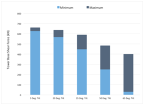
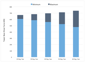
(A) Tower base shear force using tilt control. (B) Tower base shear force using yaw control.
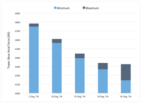
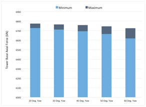
(C) Tower base axial force using tilt control. (D) Tower base axial force using yaw control.
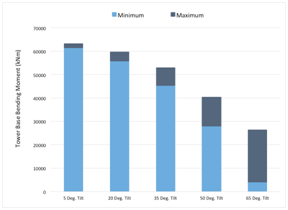

(E) Tower base bending moment using tilt control. (F) Tower base bending moment using yaw control.
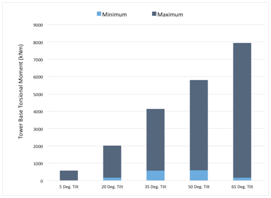
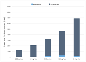
(G) Tower base torsional moment using tilt control. (H) Tower base torsional moment using yaw control
Figure 4 (A–H) Load effects predicted at tower base using tilt and yaw controls.
A similar load analysis for a two-bladed downwind wind turbine of the same size and properties was performed independently by Lee et al.21 using the FAST code.22 Figure 5 compares the average structural loads (axial force, shear force, bending moment, and torsional moment) obtained using FAST code and using the DYMORE-2 code, where the wind turbine has a 5 degrees of tilt angle. Based on the similar results obtained using two different numerical methods shown in Figure 5, it is believed that the DYMORE-2 model has been setup correctly and comparable results have been achieved in this study for the tilt and yaw control methods performed for the two-bladed downwind turbines.

Figure 5 Comparison of load effects predicted at tower base using DYMORE-2 and FAST.21
Tower top load
In the previous section, all the structural load results are shown at the base of the tower. Since the nacelle weight is applied at the top of the tower, it is crucial to investigate the various structural loads at this location and their influence on the wind turbine. The load effects are evaluated and compared on the top of the tower as show in Figures 6(A–H). The load effects at the tower top are quite similar to those at the tower base. The shear force acting at the tower top, shown in Figure 6A, decreases gradually with the increasing nacelle tilt angle. Although the same trend is present in Figure 6B using the yaw control, the reduction in shear force is miniscule when compared with the nacelle tilt control. The behavior and effect of the axial force on the tower top, shown in Figure 6C & Figure 6D, shares the same trend as seen at the tower base, but the magnitude of the load is almost one half at the tower top. The axial force continues to diminish with the increased nacelle tilt angle compared to almost a constant value using the yaw control, see Figure 6C & Figure 6D. However, the bending moment shows dissimilar outcomes when compared at two tower locations. The average values of the bending moments for all yaw angles are nearly constant, as shown in Figure 6F, in contrast to gradually reduced bending moments at the tower base as shown in Figure 4F. Furthermore, in the tilt control method, the average value of the bending moment steadily decreases with the increased nacelle tilt angles, except at 65 nacelle tilt angle where there is a large increase in the bending moment as shown in Figure 6E. Remember that the structural load acting on the top of the tower is due to combined effect of the weight of the rotor and the aerodynamic force acting on it, and at 65 degrees tilt angle, the rotor unsteady loading is at the highest level, which will be discussed later. Finally, the torsional moments seen in Figure 6G increases at higher tilt angles. The same trend occurs in Figure 6H at high yaw angles, but at a lower rate. At the tower top, the shear force causes the most fatigue damage based on the analysis.21 The simulation results obtained in this study indicate that the shear force is reduced by 67% using the nacelle tilt control, compared to 5% decrease using the yaw control as shown in Figure 6B. This implies that nacelle tilt control is the preferred control method for reducing fatigue loads on the wind turbine.
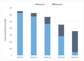
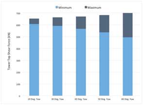
(A) Tower top shear force using tilt control. (B) Tower top shear force using yaw control.
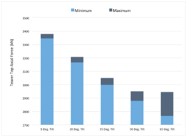
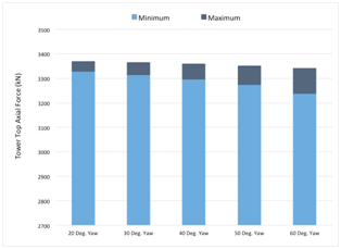
(C) Tower top axial force using tilt control. (D) Tower top axial force using yaw control.
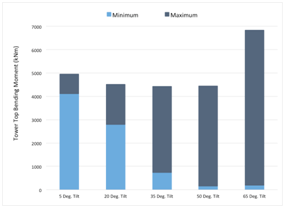
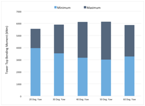
(E) Tower top bending moment using tilt control. (F) Tower top bending moment using yaw control.
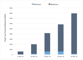
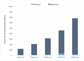
(G) Tower top torsional moment using tilt control. (H) Tower top torsional moment using yaw control.
Figure 6 (A–H) Load effects predicted at tower top using tilt and yaw controls.
The structural loads predicted at the tower top by DYMORE-2 and FAST are compared in Figure 7. Both calculations are based on the same two-bladed downwind wind turbine positioned at 5 degrees tilt angle (normal operating condition). Comparing to the loads at the tower base, there is a nearly 50% reduction of the averaged axial forces and bending moments, but virtually no change in the averaged shear forces and torsional moments. Again, all forces and moments predicted by DYMORE-2 are very close to those predicted by FAST.21
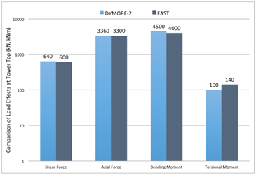
Figure 7 Comparison of load effects predicted at tower top using DYMORE-2 and FAST.21
Tower top displacement
In additional to the structural loads discussed above, the wind turbine displacement at the tower top is another key parameter to determine the structural behavior and dynamic response of the wind turbine. Figure 8(A–D) shows the out-of-plane linear displacement and the angular displacement predicted at the top of the tower. The shear force acting on the tower is mainly contributed to the out-of-plane displacement, and the angular displacement is mainly caused by the torsional moment at the tower top. At these locations the tower and blades deflect the most, so that most valuable information can be obtained in evaluating the displacement at these locations.
As shown in Figure 8A and 8B, the out-of-plane displacement continues to decrease with the increasing nacelle tilt or yaw angles. However, the linear displacement at the tower top is reduced much quicker in response to the tilt angle increase comparing to the yaw angle increase. This is because that the wind turbine operates like a helicopter mode at high tilt angles, where the aerodynamic load on the rotor is significantly reduced. The linear displacement is decreased by 77% at a higher nacelle tilt angle of 65 degrees comparing to the 5 degrees normal tilt position. On the other hand, there is a reduction of 50% linear displacement in the yaw control method from 20 to 60 degrees. These results indicate that nacelle tilt control method is superior in terms of reducing the out-of-plane displacements.
Shown in Figure 8C and Figure 8D are the torsional or angular displacements predicted at the top of the tower using both tilt and yaw control methods. The major difference seen between the two control schemes is the trend of the torsional displacement in response to the change of tilt or yaw angles. In the tilt control the torsional displacement is quickly reduced as the tilt angle increases, except for 65 degrees tilt where there is a sudden increase in the angular displacement. This trend correlates well with the behavior of the bending moment at the tower top due to increased unsteady loading on the rotor, as shown in Figure 6E. In the yaw control, however, the torsional displacement at the tower top increases consistently with the increase of yaw angles. The main observation seen from these figures is that as long as the nacelle tilt angle is less than 65 degrees, the variation of the torsional moment does not change as much in the nacelle tilt control compared to the yaw control at higher angles. However, between 35 and 50 degrees of tilt angles it is apparent that the twist displacement is also smaller than that observed using the yaw control method. In other words, the tilt control method in general provides better performance than the yaw control method in terms of both linear and angular displacements at the tower top, except at the high tilt angle of 65 degrees.
Blade root load
The blade root is a critical location to evaluate the load effects on the wind turbine rotor as well as its performance. Assessing the loads at the root of the blade will uncover some critical effects on the wind turbine such as the blade fatigue loads. Comparisons of the blade shear force, axial force, bending moment, and torsional moment at the blade root provide direct assessment of the pros and cons using both tilt control and yaw control methods.
As shown in Figure 9A, the mean shear force using the nacelle tilt control is reduced from 300kN at 5 degrees tilt angle to 115kN at 65 degrees tilt angle, which is 62% reduction compared to only 8% reduction using the yaw control, as seen in Figure 9B. However, the variation of the shear force (dark bar in the figure) increases with the tilt angle increase, which indicates larger unsteady loading at high tilt angles. Although the variation of the shear force also increases with the yaw control angle, they are not at the same extent as experienced in the tilt control. The axial forces for both tilt and yaw control methods are evaluated at all locations, as shown in Figure 9C and Figure 9D, which shows nearly the same mean value and slightly favorable outcome for the variation in the axial force in the nacelle tilt control. The blade root mean bending moment, shown in Figure 9E, slightly decreases as the nacelle tilt angle increases, while the corresponding bending moment remains almost constant using the yaw control as shown in Figure 9F. However, the variation of the blade bending moment increases significantly, especially for the tilt control method. The torsional moment in Figure 9G and Figure 9H shows the declining trend with the increasing tilt and yaw angles. However, there is a sudden increase in variation at 65 degrees tilt, as shown in Figure 9G, which indicates that the unsteady loading is at work when the wind turbine operates like a helicopter at high nacelle tilt angles. The general trend is that the mean loads acting at the blade root are decreased as the nacelle tilt angle increases, but the variances of the unsteady loads are increased with the increasing tilt angle comparing to the yaw control method. As the blade root is more vulnerable to fatigue damage from the bending moment than other turbine components,21 it is important to perform more accurate assessment of structural loads as well as dynamic response of the rotor blades at high tilt angles. This will require high fidelity simulations using computational structure dynamics (CSD) analysis coupled with computational fluid dynamics (CFD) air load prediction.20
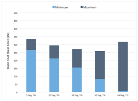
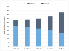
(A) Blade root shear force using tilt control. (B) Blade root shear force using yaw control.
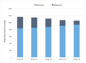
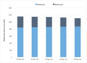
(C) Blade root axial force using tilt control. (D) Blade root axial force using yaw control.
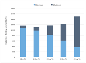
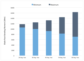
(E) Blade root bending moment using tilt control. (F) Blade root bending moment using yaw control.
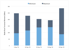
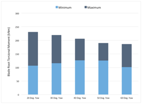
(G) Blade root torsional moment using tilt control (H) Blade root torsional moment using yaw control.
Figure 9 (A–H) Load effects predicted at blade root using tilt and yaw controls.
The accuracy of the structural loading at the blade root is assessed in Figure 10 by comparing the mean values of the shear forces, axial forces, bending moments, and torsional moments predicted at 5 degrees tilt angle using both DYMORE-2 and FAST.21 Again, all results are correlated quite well using two different methods, which indicates that general trend of structural loads on the wind turbine are predicted correctly in the present work.
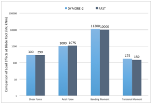
Figure 10 Comparison of load effects predicted at blade root using DYMORE-2 and FAST.21
Blade tip displacement
Like the previous discussions for the linear and angular displacements of the tower, the blade tip displacement is critical in determining the safe operation of the wind turbine. Figure 11(A–D) shows the blade out-of-plane linear displacement and angular displacement at the blade tip using both tilt control and yaw control methods. It shows that the magnitude of the out-of-plane blade tip displacements increases with angles in both tilt and yaw controls, as shown in Figure 11A and Figure 11B. However, the rotor using the tilt control seems to produce larger variations in linear displacements at high tilt angles comparing to the yaw control method at high yaw angles. In both tilt and yaw control methods, the peak out-of-plane displacements at the blade tip are nearly 10 meters, which are pretty large and should be minimized by changing the property of the blade materials.
Blade angular displacement is another indicator of the degree to which aerodynamics would be affected by deformation-based changes. Figure 11C and Figure 11D show the blade tip angular displacements using both tilt and yaw control methods. The peak angular displacement at the blade tip remains constant throughout the increasing nacelle tilt angles, except at 65 degrees tilt where there is an abrupt increase in the peak value. On the other hand, the peak angular displacement does slightly increase with the increased yaw angle, shown in Figure 11D. It appears that the mean values of the blade tip angular displacement are changed significantly, even at high nacelle tilt and yaw angles (with the peak values varying from 1.5 to 2.2 degrees).
The comparison of the blade tip linear and angular displacements using the nacelle tilt control and the yaw control shows reduced mean and peak values (linear and angular) using the nacelle tilt control method over the yaw control, except at the high tilt angle of 65 degrees. The large out-of-plane blade tip displacements may cause safety concern while the large angular displacements at the blade tip may impact the wind turbine performance and fatigue loads. To obtain complete understanding of the blade tip displacement using the above two control methods, high fidelity computational fluid dynamic analysis should be incorporated as the input for the computational structural dynamics.20
Fatigue Load
Wind turbine blades are exposed to wind loadings that cause growing fatigue damage owing to the loading’s cyclic nature. It is very crucial to detect fatigue damage during the early stages. Nowadays, the manufacturing process of wind turbine blades is greatly automated and many complications have already been eradicated. But there are still critical areas that are not feasible with prevalent inspection techniques.24 For a downwind wind turbine configuration, the wind field behind the tower is very complex to understand, consisting of turbulence and unsteady motion. The tower shadow with its turbulent unsteady vortices and mean velocity deficit is the most challenging part of a downwind wind turbine rotor. The turbulent unsteady vortices result in impetuous loading on the blades, which could contribute considerably to the blade fatigue loading as they pass through the tower influenced region.25 Wind turbine blades, which are subjected to repetitive bending, may develop cracks, which eventually could lead to complete component failure. There are various loads that contribute to fatigue in wind turbines, such as steady loads from high wind speeds, periodic loads from rotations and gravity, fatigue loads from variations in wind speed and resonance induced loads from the vibrations of structures.26
Predicting fatigue damage can be challenging due to lack of knowledge of the dynamic behavior of wind turbines.27 In this research, there is no specific fatigue analysis done in order to determine its effect on the different loadings. However, results of various forces and moments obtained at critical positions of the wind turbine from the present work can be used to perform further fatigue analysis. It has been reported that the shear forces and bending moments are the dominant components at the tower base, and the shear forces cause the most damage at the tower top.21 The present study indicates that at moderate tilt angles (less than 50 degrees) there are distinct advantages of using the tilt control in terms of reduced mean and peak loads and displacements for both the rotor blade and the tower. However, at high nacelle tilt angle of 65 degrees, the variations in displacements and bending moments grow immensely in comparison to yaw angle variations. These variations are a contributing factor to fatigue damage for the wind turbine, which should be further investigated to determine the consequence on the wind turbine fatigue loads. Further fatigue analysis should be performed in order to determine which wind turbine control method provides favorable outcomes in terms of fatigue damage to the wind turbine.
In this research, a nacelle tilt control strategy was introduced as a new method to maintain the same rated power output for the wind turbine operating at varying wind speeds. The load effects on a downwind two-bladed turbine, adapted from the NREL 5MW three-bladed reference turbine, were examined using Computational Structural Dynamics analysis. The structural loads and displacements of the wind turbine tower and rotor blade were examined at various tilt angles, which were compared with the conventional yaw control method at various yaw angles. The analysis of the nacelle tilt control method revealed favorable mean and peak loading effects at moderate tilt angles (less than 50 degrees). However, the variations in displacements and bending moments grew immensely at the high nacelle tilt angle (65 degrees) in comparison with the yaw control method, due to increased unsteady loadings acting on the rotor and the tower. This suggests that further fatigue analysis should be performed in order to quantify the impact of increased shear forces and bending moments at high tilt angles for complete assessments of this new control strategy in terms of fatigue damage to the wind turbine.
My research project was sponsored by Department of Energy with grant number DE-FG36FG36-06GO86096 and DE-EE0003540.
Authors declare there is no conflict of interest in publishing the article.

©2018 Zhao, et al. This is an open access article distributed under the terms of the, which permits unrestricted use, distribution, and build upon your work non-commercially.