Submit manuscript...
eISSN: 2574-8092

International Robotics & Automation Journal

Research Article Volume 2 Issue 2

Design and simulation of a general culinary preparation robot

Yuanqing Hong, Yuanfeng Mao, Jang Won Ko

Department of Mechanical Engineering, Columbia University, USA

Correspondence: Yuanqing Hong, Department of Mechanical Engineering, Columbia University, USA

Received: March 31, 2017 | Published: April 25, 2017

Citation: Hong Y, Mao Y, Won Ko. Design and simulation of a general culinary preparation robot. Int Rob Auto J. 2017;2(2):61-64. DOI: 10.15406/iratj.2017.02.00017

Download PDF

Abstract

Modern kitchens involve many repetitious and arduous tasks that are currently completed with human labor. This paper presents a general purpose culinary preparation anthropomorphic robot to help people peeling spherical fruit. The trajectory of the end effectors is designed to move along the skin of the spherical fruit. In addition, an obstacle avoidance algorithm is provided to solve the potential collision problems. Methodologies and results of simulation are presented and discussed.

Keywords: anthropomorphic robot, trajectory planning, end effector, obstacle avoidance

Introduction

Robotics and automation has boomed in the food industry recently, but this has primarily been driven by large manufacturers and restaurant ordering.1 Especially for small and medium sized restaurants preparation continues to be done primarily by hand.2 In the United States, minimum wage is set to increase to $15/hour in many cities and nearly a third of all money spent on food is being spent eating out at restaurants. As such, we are presented with a unique opportunity for automation to disrupt the industry and drive more affordable food.3 Additionally, and labor already contributed to 38.5% of all food costs in 1997, and has continued to grow at an average of 3.1% annually from 1987 to 2015.4,5 There is a significant body of research on general purpose robots suitable for such tasks. However, current robots used for such tasks are highly customized and not generalizable.6 A commonly used peeling machine is one that fixes a fruit to an axis and uses a rotating handle to peel off the skin, which clearly does not extend to other tasks outside of peeling.7 There are many other similar examples that are likewise constrained to a single use case, such as one to peel mangos, another for melons, and multiple for tomatoes.8

Through this survey we honed in on anthropomorphic arm designs with variable end effectors. In particular, we have identified the PUMA as a strong choice and used the design in our simulations.9 The primary goal of this paper is to present a working simulation of a general-purpose arm along with programming to complete one food preparation task. The task must be representative of the technical difficulty found in this set of tasks. We selected the task of peeling spherical fruit, and present the software to control robotic arm to peel arbitrary spherical fruit, customized to arbitrary precision and parameterized to loss allow the user to control the tradeoff between speed and precision.

Mathematical models

Modeling for Circular Fruit

We chose to model fruit all as perfect spheres. Citrus fruit have a useful structure with an outer peel called the Flavedo (referred to as “peel”), an inner shell called the Albedo (“pulp”) both wrapping the Mesocarp (“center”). Our simulation models all three as perfect spheres, where the constraints are that the peel must be entirely removed, the pulp may be partially removed, and the center may not be removed at all. Modelling all fruit as citrus fruit proves extensible to other types. While we can perfectly track the central sphere across one axis, due to the end effector being planar there is a cross axis for which we take linear cross sections; see Figure 1. For citrus fruit, we determine this cross section through the radius of the pulp sphere, for other fruit we specify a corresponding depth which will be removed from the central sphere. In our simulated fruit, we normalize the sphere to be a unit sphere, and allow the radius of the peel and pulp to be specified relative to the unit sphere. Given the linear cross sections we are not able to retain a Perfect spherical and thus approximate the shape of the sphere as we cut it. As such, we accept arbitrarily resolution for the sphere taken as the number of discrete points across each of the three dimensions of the sphere creating a three-dimensional grid. The sphere then takes the translation in the X, Y and Z dimensions to project itself into the coordinate system of the arm along with the radius of the sphere also in the arms coordinate system. As we define the sphere as O( K N 3 ) MathType@MTEF@5@5@+= feaagKart1ev2aaatCvAUfeBSjuyZL2yd9gzLbvyNv2CaerbuLwBLn hiov2DGi1BTfMBaeXatLxBI9gBaerbd9wDYLwzYbItLDharqqtubsr 4rNCHbGeaGqiVCI8FfYJH8YrFfeuY=Hhbbf9v8qqaqFr0xc9pk0xbb a9q8WqFfeaY=biLkVcLq=JHqpepeea0=as0Fb9pgeaYRXxe9vr0=vr 0=vqpWqaaeaabiGaciaacaqabeaadaqaaqaaaOqaaKqbakaad+eada qadaqaaiaadUeacqGHxiIkcaWGobWaaWbaaKqbGeqabaGaaG4maaaa aKqbakaawIcacaGLPaaaaaa@3D03@ an approximation of N 3 MathType@MTEF@5@5@+= feaagKart1ev2aaatCvAUfeBSjuyZL2yd9gzLbvyNv2CaerbuLwBLn hiov2DGi1BTfMBaeXatLxBI9gBaerbd9wDYLwzYbItLDharqqtubsr 4rNCHbGeaGqiVCI8FfYJH8YrFfeuY=Hhbbf9v8qqaqFr0xc9pk0xbb a9q8WqFfeaY=biLkVcLq=JHqpepeea0=as0Fb9pgeaYRXxe9vr0=vr 0=vqpWqaaeaabiGaciaacaqabeaadaqaaqaaaOqaaKqbakaad6eada ahaaqcfasabeaacaaIZaaaaaaa@3859@ points, and take in K paths to compute, the runtime to display the sphere is as for each cut we iterate over all points to see if these intersect. We compute multiple squares within these, but multiplication is a constant time operation for a fixed precision float. The depth of the pulp (D) determines the number of rotations along the cross section via θ MathType@MTEF@5@5@+= feaagKart1ev2aaatCvAUfeBSjuyZL2yd9gzLbvyNv2CaerbuLwBLn hiov2DGi1BTfMBaeXatLxBI9gBaerbd9wDYLwzYbItLDharqqtubsr 4rNCHbGeaGqiVCI8FfYJH8YrFfeuY=Hhbbf9v8qqaqFr0xc9pk0xbb a9q8WqFfeaY=biLkVcLq=JHqpepeea0=as0Fb9pgeaYRXxe9vr0=vr 0=vqpWqaaeaabiGaciaacaqabeaadaqaaqaaaOqaaKqbakabeI7aXb aa@382F@ , the interval angle on our off axis. This can be derived simply by normalizing the pulp and center spheres to a unit sphere.
Figure 1 The cross section of a fruit on the off axis.

Modeling for the Robotic Arm

The aim of the simulation is to visualize and validate the performance of anthropomorphic arm. The DH table (Table 1) parameters were calculated associated with a complex industrial robot PUMA560. We listed a few constraints which must be taken into consideration in real-world use. Other considerations were given to the control algorithm. The trajectory of the end-effector was carefully designed to model circular fruit. The orientation of the end-effector was specified to suit the chosen type of the blade and to avoid collision with the fruit. These program design decisions are detailed in this section. In addition, some plotting results in MATLAB of the animation of the robot are presented. A 3D model was designed9 with four links was designed as shown in Figure 2. It has an anthropomorphic arm shape; the four links represent a torso, an upper-arm, a lower-arm and an end effector, respectively. Moreover, three revolute joints are used to achieve 6 degree of freedom. The structure of the end effector was inspired by the cutting tools of milling and lathe machine; the blade is perpendicular to the surface being cut. The blades of the end effector are designed in Figure 3 to be straight instead of curved, as curved blades would limit the geometry of the fruit being cut. In this project, the blade was assumed to be an ideal one; it would cut instantly as it touches an object.

Link

a i MathType@MTEF@5@5@+= feaagKart1ev2aaatCvAUfeBSjuyZL2yd9gzLbvyNv2CaerbuLwBLn hiov2DGi1BTfMBaeXatLxBI9gBaerbd9wDYLwzYbItLDharqqtubsr 4rNCHbGeaGqiVCI8FfYJH8YrFfeuY=Hhbbf9v8qqaqFr0xc9pk0xbb a9q8WqFfeaY=biLkVcLq=JHqpepeea0=as0Fb9pgeaYRXxe9vr0=vr 0=vqpWqaaeaabiGaciaacaqabeaadaqaaqaaaOqaaKqbakaadggada WgaaqcfasaaiaadMgaaeqaaaaa@389C@

α i MathType@MTEF@5@5@+= feaagKart1ev2aaatCvAUfeBSjuyZL2yd9gzLbvyNv2CaerbuLwBLn hiov2DGi1BTfMBaeXatLxBI9gBaerbd9wDYLwzYbItLDharqqtubsr 4rNCHbGeaGqiVCI8FfYJH8YrFfeuY=Hhbbf9v8qqaqFr0xc9pk0xbb a9q8WqFfeaY=biLkVcLq=JHqpepeea0=as0Fb9pgeaYRXxe9vr0=vr 0=vqpWqaaeaabiGaciaacaqabeaadaqaaqaaaOqaaKqbakabeg7aHn aaBaaajuaibaGaamyAaaqabaaaaa@3955@

d i MathType@MTEF@5@5@+= feaagKart1ev2aaatCvAUfeBSjuyZL2yd9gzLbvyNv2CaerbuLwBLn hiov2DGi1BTfMBaeXatLxBI9gBaerbd9wDYLwzYbItLDharqqtubsr 4rNCHbGeaGqiVCI8FfYJH8YrFfeuY=Hhbbf9v8qqaqFr0xc9pk0xbb a9q8WqFfeaY=biLkVcLq=JHqpepeea0=as0Fb9pgeaYRXxe9vr0=vr 0=vqpWqaaeaabiGaciaacaqabeaadaqaaqaaaOqaaKqbakaadsgada WgaaqcfasaaiaadMgaaeqaaaaa@389F@

θ i MathType@MTEF@5@5@+= feaagKart1ev2aaatCvAUfeBSjuyZL2yd9gzLbvyNv2CaerbuLwBLn hiov2DGi1BTfMBaeXatLxBI9gBaerbd9wDYLwzYbItLDharqqtubsr 4rNCHbGeaGqiVCI8FfYJH8YrFfeuY=Hhbbf9v8qqaqFr0xc9pk0xbb a9q8WqFfeaY=biLkVcLq=JHqpepeea0=as0Fb9pgeaYRXxe9vr0=vr 0=vqpWqaaeaabiGaciaacaqabeaadaqaaqaaaOqaaKqbakabeI7aXn aaBaaajuaibaGaamyAaaqabaaaaa@396C@

1

0

0

θ 1 * MathType@MTEF@5@5@+= feaagKart1ev2aaatCvAUfeBSjuyZL2yd9gzLbvyNv2CaerbuLwBLn hiov2DGi1BTfMBaeXatLxBI9gBaerbd9wDYLwzYbItLDharqqtubsr 4rNCHbGeaGqiVCI8FfYJH8YrFfeuY=Hhbbf9v8qqaqFr0xc9pk0xbb a9q8WqFfeaY=biLkVcLq=JHqpepeea0=as0Fb9pgeaYRXxe9vr0=vr 0=vqpWqaaeaabiGaciaacaqabeaadaqaaqaaaOqaaKqbakabeI7aXn aaDaaajuaibaGaaGymaaqaaiaacQcaaaaaaa@39E8@

2

0

-90°

0

θ 2 * MathType@MTEF@5@5@+= feaagKart1ev2aaatCvAUfeBSjuyZL2yd9gzLbvyNv2CaerbuLwBLn hiov2DGi1BTfMBaeXatLxBI9gBaerbd9wDYLwzYbItLDharqqtubsr 4rNCHbGeaGqiVCI8FfYJH8YrFfeuY=Hhbbf9v8qqaqFr0xc9pk0xbb a9q8WqFfeaY=biLkVcLq=JHqpepeea0=as0Fb9pgeaYRXxe9vr0=vr 0=vqpWqaaeaabiGaciaacaqabeaadaqaaqaaaOqaaKqbakabeI7aXn aaDaaajuaibaGaaGOmaaqaaiaacQcaaaaaaa@39E9@

3

a 3 MathType@MTEF@5@5@+= feaagKart1ev2aaatCvAUfeBSjuyZL2yd9gzLbvyNv2CaerbuLwBLn hiov2DGi1BTfMBaeXatLxBI9gBaerbd9wDYLwzYbItLDharqqtubsr 4rNCHbGeaGqiVCI8FfYJH8YrFfeuY=Hhbbf9v8qqaqFr0xc9pk0xbb a9q8WqFfeaY=biLkVcLq=JHqpepeea0=as0Fb9pgeaYRXxe9vr0=vr 0=vqpWqaaeaabiGaciaacaqabeaadaqaaqaaaOqaaKqbakaadggada Wgaaqcfasaaiaaiodaaeqaaaaa@386B@

d 3 MathType@MTEF@5@5@+= feaagKart1ev2aaatCvAUfeBSjuyZL2yd9gzLbvyNv2CaerbuLwBLn hiov2DGi1BTfMBaeXatLxBI9gBaerbd9wDYLwzYbItLDharqqtubsr 4rNCHbGeaGqiVCI8FfYJH8YrFfeuY=Hhbbf9v8qqaqFr0xc9pk0xbb a9q8WqFfeaY=biLkVcLq=JHqpepeea0=as0Fb9pgeaYRXxe9vr0=vr 0=vqpWqaaeaabiGaciaacaqabeaadaqaaqaaaOqaaKqbakaadsgada Wgaaqcfasaaiaaiodaaeqaaaaa@386E@

θ 3 * MathType@MTEF@5@5@+= feaagKart1ev2aaatCvAUfeBSjuyZL2yd9gzLbvyNv2CaerbuLwBLn hiov2DGi1BTfMBaeXatLxBI9gBaerbd9wDYLwzYbItLDharqqtubsr 4rNCHbGeaGqiVCI8FfYJH8YrFfeuY=Hhbbf9v8qqaqFr0xc9pk0xbb a9q8WqFfeaY=biLkVcLq=JHqpepeea0=as0Fb9pgeaYRXxe9vr0=vr 0=vqpWqaaeaabiGaciaacaqabeaadaqaaqaaaOqaaKqbakabeI7aXn aaDaaajuaibaGaaG4maaqaaiaacQcaaaaaaa@39EA@

4

a 4 MathType@MTEF@5@5@+= feaagKart1ev2aaatCvAUfeBSjuyZL2yd9gzLbvyNv2CaerbuLwBLn hiov2DGi1BTfMBaeXatLxBI9gBaerbd9wDYLwzYbItLDharqqtubsr 4rNCHbGeaGqiVCI8FfYJH8YrFfeuY=Hhbbf9v8qqaqFr0xc9pk0xbb a9q8WqFfeaY=biLkVcLq=JHqpepeea0=as0Fb9pgeaYRXxe9vr0=vr 0=vqpWqaaeaabiGaciaacaqabeaadaqaaqaaaOqaaKqbakaadggada Wgaaqcfasaaiaaisdaaeqaaaaa@386C@

-90°

d 4 MathType@MTEF@5@5@+= feaagKart1ev2aaatCvAUfeBSjuyZL2yd9gzLbvyNv2CaerbuLwBLn hiov2DGi1BTfMBaeXatLxBI9gBaerbd9wDYLwzYbItLDharqqtubsr 4rNCHbGeaGqiVCI8FfYJH8YrFfeuY=Hhbbf9v8qqaqFr0xc9pk0xbb a9q8WqFfeaY=biLkVcLq=JHqpepeea0=as0Fb9pgeaYRXxe9vr0=vr 0=vqpWqaaeaabiGaciaacaqabeaadaqaaqaaaOqaaKqbakaadsgada Wgaaqcfasaaiaaisdaaeqaaaaa@386F@

θ 4 * MathType@MTEF@5@5@+= feaagKart1ev2aaatCvAUfeBSjuyZL2yd9gzLbvyNv2CaerbuLwBLn hiov2DGi1BTfMBaeXatLxBI9gBaerbd9wDYLwzYbItLDharqqtubsr 4rNCHbGeaGqiVCI8FfYJH8YrFfeuY=Hhbbf9v8qqaqFr0xc9pk0xbb a9q8WqFfeaY=biLkVcLq=JHqpepeea0=as0Fb9pgeaYRXxe9vr0=vr 0=vqpWqaaeaabiGaciaacaqabeaadaqaaqaaaOqaaKqbakabeI7aXn aaDaaajuaibaGaaGinaaqaaiaacQcaaaaaaa@39EB@

5

0

90°

0

θ 5 * MathType@MTEF@5@5@+= feaagKart1ev2aaatCvAUfeBSjuyZL2yd9gzLbvyNv2CaerbuLwBLn hiov2DGi1BTfMBaeXatLxBI9gBaerbd9wDYLwzYbItLDharqqtubsr 4rNCHbGeaGqiVCI8FfYJH8YrFfeuY=Hhbbf9v8qqaqFr0xc9pk0xbb a9q8WqFfeaY=biLkVcLq=JHqpepeea0=as0Fb9pgeaYRXxe9vr0=vr 0=vqpWqaaeaabiGaciaacaqabeaadaqaaqaaaOqaaKqbakabeI7aXn aaDaaajuaibaGaaGynaaqaaiaacQcaaaaaaa@39EC@

6

0

-90°

0

θ 6 * MathType@MTEF@5@5@+= feaagKart1ev2aaatCvAUfeBSjuyZL2yd9gzLbvyNv2CaerbuLwBLn hiov2DGi1BTfMBaeXatLxBI9gBaerbd9wDYLwzYbItLDharqqtubsr 4rNCHbGeaGqiVCI8FfYJH8YrFfeuY=Hhbbf9v8qqaqFr0xc9pk0xbb a9q8WqFfeaY=biLkVcLq=JHqpepeea0=as0Fb9pgeaYRXxe9vr0=vr 0=vqpWqaaeaabiGaciaacaqabeaadaqaaqaaaOqaaKqbakabeI7aXn aaDaaajuaibaGaaGOnaaqaaiaacQcaaaaaaa@39ED@

Table 1 DH table for PUMA560

Figure 2 The 3D model of PUMA560.
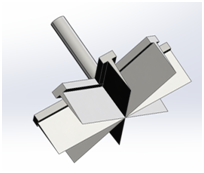
Figure 3 New designed end effector.

Robotic control flow

Careful consideration was given to the control algorithm of the robot. The trajectory of the end-effector was designed to traverse the perimeter of the spherical fruit. The orientation of the end-effector was specified to suit the chosen type of the blade as well as avoiding collision with the fruit. These program design decisions are detailed in this section. Some plotting results in MATLAB of the animation of the robot are presented. In addition, a particular solution to remove the whole peel of the fruit, complete with obstacle avoidance, is given.

Motion planning

Based on the position and orientation of the end-effector, a set of solutions were calculated to control each link. The spherical trajectory of the end-effector was designed using sphere equations in 3D space (as shown in Figure 4, defined as follows,10 in which R is the radius of the sphere:

x= O x +Rsinφcosθ y= O y +Rcosφsinθ z= O z +Rcosθ MathType@MTEF@5@5@+= feaagKart1ev2aaatCvAUfeBSjuyZL2yd9gzLbvyNv2CaerbuLwBLn hiov2DGi1BTfMBaeXatLxBI9gBaerbd9wDYLwzYbItLDharqqtubsr 4rNCHbGeaGqiVCI8FfYJH8YrFfeuY=Hhbbf9v8qqaqFr0xc9pk0xbb a9q8WqFfeaY=biLkVcLq=JHqpepeea0=as0Fb9pgeaYRXxe9vr0=vr 0=vqpWqaaeaabiGaciaacaqabeaadaqaaqaaaOabaeqabaqcfaOaam iEaiabg2da9iaad+eadaWgaaqcfasaaiaadIhaaKqbagqaaiabgUca RiaadkfaciGGZbGaaiyAaiaac6gacqaHgpGAciGGJbGaai4Baiaaco hacqaH4oqCaeaacaWG5bGaeyypa0Jaam4tamaaBaaajuaibaGaamyE aaqcfayabaGaey4kaSIaamOuaiGacogacaGGVbGaai4CaiabeA8aQj GacohacaGGPbGaaiOBaiabeI7aXbqaaiaadQhacqGH9aqpcaWGpbWa aSbaaKqbGeaacaWG6baajuaGbeaacqGHRaWkcaWGsbGaci4yaiaac+ gacaGGZbGaeqiUdehaaaa@608A@

The trajectory was divided into several circles connected by a vertical path along its diameter. Each loop consisted of finite points as defined by the spherical equations to approximate a perfectly smooth circle. The end-effector starts from the top intersection point, and move along the vertical guideline, removing one circle of peel each time. The position of x,y,z varying with time was shown in Figure 5.
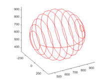
Figure 4 Spherical trajectory of end effector.
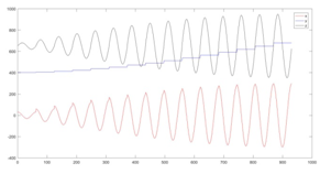
Figure 5 The position of x,y,z.

Inverse Kinematics

To transform the motion trajectory into joint actuator trajectories for the robot, a common methodology is to conduct inverse kinematics. Given the position and orientation of the end-effector we are able to calculate the joint parameters using kinematic equations. To define the orientation of end-effector, we first define and set up frames for each point on the trajectory as follows.11 Z-axis: normal to surface pointing at center of the sphere. X-axis: parallel to moving direction. Y-axis:cross product of vector Z and X. Denoting the position of center point of sphere as [ O x , O y , O z ] MathType@MTEF@5@5@+= feaagKart1ev2aqatCvAUfeBSjuyZL2yd9gzLbvyNv2CaerbuLwBLn hiov2DGi1BTfMBaeXatLxBI9gBaerbd9wDYLwzYbItLDharqqtubsr 4rNCHbGeaGqiVCI8FfYJH8YrFfeuY=Hhbbf9v8qqaqFr0xc9pk0xbb a9q8WqFfeaY=biLkVcLq=JHqpepeea0=as0Fb9pgeaYRXxe9vr0=vr 0=vqpWqaaeaabiGaciaacaqabeaadaqaaqaaaOqaaKqbaoaadmaaba Gaam4tamaaBaaajuaibaGaamiEaaqcfayabaGaaiilaiaad+eadaWg aaqcfasaaiaadMhaaKqbagqaaiaacYcacaWGpbWaaSbaaKqbGeaaca WG6baajuaGbeaaaiaawUfacaGLDbaaaaa@41D9@ , and the position of wrist as [ o x , o y , o z ] MathType@MTEF@5@5@+= feaagKart1ev2aqatCvAUfeBSjuyZL2yd9gzLbvyNv2CaerbuLwBLn hiov2DGi1BTfMBaeXatLxBI9gBaerbd9wDYLwzYbItLDharqqtubsr 4rNCHbGeaGqiVCI8FfYJH8YrFfeuY=Hhbbf9v8qqaqFr0xc9pk0xbb a9q8WqFfeaY=biLkVcLq=JHqpepeea0=as0Fb9pgeaYRXxe9vr0=vr 0=vqpWqaaeaabiGaciaacaqabeaadaqaaqaaaOqaaKqbaoaadmaaba Gaam4BamaaBaaajuaibaGaamiEaaqabaqcfaOaaiilaiaad+gadaWg aaqcfasaaiaadMhaaKqbagqaaiaacYcacaWGVbWaaSbaaKqbGeaaca WG6baajuaGbeaaaiaawUfacaGLDbaaaaa@4239@ . The relative orientation of end-effector to original coordinate can be expressed as:

R z = [ O x o x , O y o y , O z o z ] MathType@MTEF@5@5@+= feaagKart1ev2aqatCvAUfeBSjuyZL2yd9gzLbvyNv2CaerbuLwBLn hiov2DGi1BTfMBaeXatLxBI9gBaerbd9wDYLwzYbItLDharqqtubsr 4rNCHbGeaGqiVCI8FfYJH8YrFfeuY=Hhbbf9v8qqaqFr0xc9pk0xbb a9q8WqFfeaY=biLkVcLq=JHqpepeea0=as0Fb9pgeaYRXxe9vr0=vr 0=vqpWqaaeaabiGaciaacaqabeaadaqaaqaaaOqaaKqbakaadkfada WgaaqcfasaaiaadQhaaKqbagqaaiabg2da9abaaaaaaaaapeGaaiiO a8aadaWadaqaaiaad+eadaWgaaqcfasaaiaadIhaaKqbagqaaiabgk HiTiaad+gadaWgaaqcfasaaiaadIhaaeqaaKqbakaacYcacaWGpbWa aSbaaKqbGeaacaWG5baabeaajuaGcqGHsislcaWGVbWaaSbaaKqbGe aacaWG5baajuaGbeaacaGGSaGaam4tamaaBaaajuaibaGaamOEaaqc fayabaGaeyOeI0Iaam4BamaaBaaajuaibaGaamOEaaqcfayabaaaca GLBbGaayzxaaaaaa@5219@

R z = [ P ˙ x ,0, P ˙ z ] MathType@MTEF@5@5@+= feaagKart1ev2aqatCvAUfeBSjuyZL2yd9gzLbvyNv2CaerbuLwBLn hiov2DGi1BTfMBaeXatLxBI9gBaerbd9wDYLwzYbItLDharqqtubsr 4rNCHbGeaGqiVCI8FfYJH8YrFfeuY=Hhbbf9v8qqaqFr0xc9pk0xbb a9q8WqFfeaY=biLkVcLq=JHqpepeea0=as0Fb9pgeaYRXxe9vr0=vr 0=vqpWqaaeaabiGaciaacaqabeaadaqaaqaaaOqaaKqbakaadkfada WgaaqcfasaaiaadQhaaKqbagqaaiabg2da9abaaaaaaaaapeGaaiiO amaadmaabaGabmiuayaacaWaaSbaaKqbGeaacaWG4baajuaGbeaaca GGSaGaaGimaiaacYcaceWGqbGbaiaadaWgaaqcfasaaiaadQhaaeqa aaqcfaOaay5waiaaw2faaaaa@44F5@

R y =  R ¯ z × R ¯ x MathType@MTEF@5@5@+= feaagKart1ev2aqatCvAUfeBSjuyZL2yd9gzLbvyNv2CaerbuLwBLn hiov2DGi1BTfMBaeXatLxBI9gBaerbd9wDYLwzYbItLDharqqtubsr 4rNCHbGeaGqiVCI8FfYJH8YrFfeuY=Hhbbf9v8qqaqFr0xc9pk0xbb a9q8WqFfeaY=biLkVcLq=JHqpepeea0=as0Fb9pgeaYRXxe9vr0=vr 0=vqpWqaaeaabiGaciaacaqabeaadaqaaqaaaOqaaKqbakaadkfada WgaaqcfasaaiaadMhaaKqbagqaaiabg2da9abaaaaaaaaapeGaaiiO aiqackfagaqeamaaBaaajuaibaGaamOEaaqcfayabaGaey41aqRabm OuayaaraWaaSbaaKqbGeaacaWG4baajuaGbeaaaaa@4320@

Therefore, the rotation matrix of the end-effector is:

R = [ R x , R y , R z ] = [ r 11 r 12 r 13 r 21 r 22 r 23 r 31 r 32 r 33 ] p x  =  o x d 6 r 13 p y  =  o y d 6 r 23 p z  =  o z d 6 r 33 MathType@MTEF@5@5@+= feaagKart1ev2aaatCvAUfeBSjuyZL2yd9gzLbvyNv2CaerbuLwBLn hiov2DGi1BTfMBaeXatLxBI9gBaerbd9wDYLwzYbItLDharqqtubsr 4rNCHbGeaGqiVCI8FfYJH8YrFfeuY=Hhbbf9v8qqaqFr0xc9pk0xbb a9q8WqFfeaY=biLkVcLq=JHqpepeea0=as0Fb9pgeaYRXxe9vr0=vr 0=vqpWqaaeaabiGaciaacaqabeaadaqaaqaaaOabaeqabaqcfaOaam OuaabaaaaaaaaapeGaaiiOa8aacqGH9aqppeGaaiiOa8aadaWadaqa aiaadkfadaWgaaqcfasaaiaadIhaaKqbagqaaiaacYcacaWGsbWaaS baaKqbGeaacaWG5baabeaajuaGcaGGSaGaamOuamaaBaaajuaibaGa amOEaaqcfayabaaacaGLBbGaayzxaaWdbiaacckapaGaeyypa0Zdbi aacckapaWaamWaaeaafaqabeWadaaabaGaamOCamaaBaaajuaibaGa aGymaiaaigdaaKqbagqaaaqaaiaadkhadaWgaaqcfasaaiaaigdaca aIYaaajuaGbeaaaeaacaWGYbWaaSbaaKqbGeaacaaIXaGaaG4maaqc fayabaaabaGaamOCamaaBaaajuaibaGaaGOmaiaaigdaaKqbagqaaa qaaiaadkhadaWgaaqcfasaaiaaikdacaaIYaaajuaGbeaaaeaacaWG YbWaaSbaaKqbGeaacaaIYaGaaG4maaqcfayabaaabaGaamOCamaaBa aajuaibaGaaG4maiaaigdaaKqbagqaaaqaaiaadkhadaWgaaqcfasa aiaaiodacaaIYaaajuaGbeaaaeaacaWGYbWaaSbaaKqbGeaacaaIZa GaaG4maaqcfayabaaaaaGaay5waiaaw2faaaqaaiaadchadaWgaaqa aKqbGiaadIhajuaGpeGaaiiOaaWdaeqaaiabg2da98qacaGGGcGaam 4BamaaBaaajuaibaGaamiEaaqcfayabaGaeyOeI0IaamizamaaBaaa juaibaGaaGOnaaqcfayabaGaamOCamaaBaaajuaibaGaaGymaiaaio daaKqbagqaaaqaa8aacaWGWbWaaSbaaKqbGeaapeGaaiyEaiaaccka a8aabeaajuaGcqGH9aqppeGaaiiOaiaad+gadaWgaaqcfasaaiaadM haaKqbagqaaiabgkHiTiaadsgadaWgaaqcfasaaiaaiAdaaKqbagqa aiaadkhadaWgaaqcfasaaiaaikdacaaIZaaajuaGbeaaaeaapaGaam iCamaaBaaajuaibaWdbiaacQhacaGGGcaapaqabaqcfaOaeyypa0Zd biaacckacaWGVbWaaSbaaKqbGeaacaWG6baajuaGbeaacqGHsislca WGKbWaaSbaaKqbGeaacaaI2aaajuaGbeaacaWGYbWaaSbaaKqbGeaa caaIZaGaaG4maaqcfayabaaaaaa@994E@

In this way, the end-effector will always be perpendicular to the surface of sphere.
After obtain the rotation matrix end end-effector, we can calculate the six joints by following formulas:

θ 1 =Atan( p x , p y ) θ 3 =Atan( D,± 1 D 2 ) θ 2 =Atan( p x 2 + p x 2 ) θ 4 =Atan( c 1 c 23 r 13 + s 1 c 23 r 23 s 23 r 23 c 1 s 23 r 13 s 1 s 23 r 23 c 23 r 33 ) θ 5 =Atan( s 1 r 13 c 1 r 23 , 1 ( s 1 r 13 c 1 r 23 ) 2 ) θ 6 =Atan( s 1 r 11 c 1 r 21 , s 1 r 12 c 1 r 22 ) MathType@MTEF@5@5@+= feaagKart1ev2aaatCvAUfeBSjuyZL2yd9gzLbvyNv2CaerbuLwBLn hiov2DGi1BTfMBaeXatLxBI9gBaerbd9wDYLwzYbItLDharqqtubsr 4rNCHbGeaGqiVCI8FfYJH8YrFfeuY=Hhbbf9v8qqaqFr0xc9pk0xbb a9q8WqFfeaY=biLkVcLq=JHqpepeea0=as0Fb9pgeaYRXxe9vr0=vr 0=vqpWqaaeaabiGaciaacaqabeaadaqaaqaaaOabaeqabaqcfaOaeq iUde3aaSbaaKqbGeaacaaIXaaajuaGbeaacqGH9aqpcaWGbbGaciiD aiaacggacaGGUbWaaeWaaeaacaWGWbWaaSbaaKqbGeaacaWG4baaju aGbeaacaGGSaGaamiCamaaBaaajuaibaGaamyEaaqcfayabaaacaGL OaGaayzkaaaabaGaeqiUde3aaSbaaKqbGeaacaaIZaaabeaajuaGcq GH9aqpcaWGbbGaciiDaiaacggacaGGUbWaaeWaaeaacaWGebGaaiil aiabgglaXoaakaaabaGaaGymaiabgkHiTiaadseadaahaaqabKqbGe aacaaIYaaaaaqcfayabaaacaGLOaGaayzkaaaabaGaeqiUde3aaSba aKqbGeaacaaIYaaabeaajuaGcqGH9aqpcaWGbbGaciiDaiaacggaca GGUbWaaeWaaeaadaGcaaqaaiaadchadaWgaaqcfasaaiaadIhaaeqa aKqbaoaaCaaajuaibeqaaiaaikdaaaqcfaOaey4kaSIaamiCamaaBa aajuaibaGaamiEaaqcfayabaWaaWbaaKqbGeqabaGaaGOmaaaaaKqb agqaaaGaayjkaiaawMcaaaqaaiabeI7aXnaaBaaajuaibaGaaGinaa qcfayabaGaeyypa0JaamyqaiGacshacaGGHbGaaiOBamaabmaabaGa am4yamaaBaaajuaibaGaaGymaaqabaqcfaOaam4yamaaBaaabaqcfa IaaGOmaiaaiodaaKqbagqaaiaadkhadaWgaaqcfasaaiaaigdacaaI ZaaajuaGbeaacqGHRaWkcaWGZbWaaSbaaKqbGeaacaaIXaaajuaGbe aacaWGJbWaaSbaaKqbGeaacaaIYaGaaG4maaqabaqcfaOaamOCamaa BaaajuaibaGaaGOmaiaaiodaaKqbagqaaiabgkHiTiaadohadaWgaa qcfasaaiaaikdacaaIZaaajuaGbeaacaWGYbWaaSbaaKqbGeaacaaI YaGaaG4maaqabaqcfaOaeyOeI0Iaam4yamaaBaaajuaibaGaaGymaa qabaqcfaOaam4CamaaBaaajuaibaGaaGOmaiaaiodaaKqbagqaaiaa dkhadaWgaaqcfasaaiaaigdacaaIZaaabeaajuaGcqGHsislcaWGZb WaaSbaaKqbGeaacaaIXaaajuaGbeaacaWGZbWaaSbaaKqbGeaacaaI YaGaaG4maaqcfayabaGaamOCamaaBaaajuaibaGaaGOmaiaaiodaaK qbagqaaiabgkHiTiaadogadaWgaaqcfasaaiaaikdacaaIZaaajuaG beaacaWGYbWaaSbaaKqbGeaacaaIZaGaaG4maaqcfayabaaacaGLOa GaayzkaaaabaGaeqiUde3aaSbaaKqbGeaacaaI1aaabeaajuaGcqGH 9aqpcaWGbbGaciiDaiaacggacaGGUbWaaeWaaeaacaWGZbWaaSbaaK qbGeaacaaIXaaabeaajuaGcaWGYbWaaSbaaKqbGeaacaaIXaGaaG4m aaqcfayabaGaeyOeI0Iaam4yamaaBaaajuaibaGaaGymaaqabaqcfa OaamOCamaaBaaajuaibaGaaGOmaiaaiodaaKqbagqaaiaacYcadaGc aaqaaiaaigdacqGHsisldaqadaqaaiaadohadaWgaaqcfasaaiaaig daaeqaaKqbakaadkhadaWgaaqcfasaaiaaigdacaaIZaaabeaajuaG cqGHsislcaWGJbWaaSbaaKqbGeaacaaIXaaajuaGbeaacaWGYbWaaS baaKqbGeaacaaIYaGaaG4maaqcfayabaaacaGLOaGaayzkaaWaaWba aeqajuaibaGaaGOmaaaaaKqbagqaaaGaayjkaiaawMcaaaqaaiabeI 7aXnaaBaaajuaibaGaaGOnaaqcfayabaGaeyypa0JaamyqaiGacsha caGGHbGaaiOBamaabmaabaGaam4CamaaBaaajuaibaGaaGymaaqaba qcfaOaamOCamaaBaaajuaibaGaaGymaiaaigdaaKqbagqaaiabgkHi TiaadogadaWgaaqcfasaaiaaigdaaeqaaKqbakaadkhadaWgaaqcfa saaiaaikdacaaIXaaajuaGbeaacaGGSaGaam4CamaaBaaajuaibaGa aGymaaqabaqcfaOaamOCamaaBaaajuaibaGaaGymaiaaikdaaKqbag qaaiabgkHiTiaadogadaWgaaqcfasaaiaaigdaaeqaaKqbakaadkha daWgaaqcfasaaiaaikdacaaIYaaajuaGbeaaaiaawIcacaGLPaaaaa aa@F594@

Where D =  p x 2 + p y 2 + ( p z d 1 ) 2 a 2 2 d 4 2 2 a 2 d 4 MathType@MTEF@5@5@+= feaagKart1ev2aaatCvAUfeBSjuyZL2yd9gzLbvyNv2CaerbuLwBLn hiov2DGi1BTfMBaeXatLxBI9gBaerbd9wDYLwzYbItLDharqqtubsr 4rNCHbGeaGqiVCI8FfYJH8YrFfeuY=Hhbbf9v8qqaqFr0xc9pk0xbb a9q8WqFfeaY=biLkVcLq=JHqpepeea0=as0Fb9pgeaYRXxe9vr0=vr 0=vqpWqaaeaabiGaciaacaqabeaadaqaaqaaaOqaaKqbakaadseaqa aaaaaaaaWdbiaacckapaGaeyypa0ZdbiaacckapaWaaSaaaeaacaWG WbWaa0baaKqbGeaacaWG4baabaGaaGOmaaaajuaGcqGHRaWkcaWGWb Waa0baaKqbGeaacaWG5baabaGaaGOmaaaajuaGcqGHRaWkdaqadaqa aiaadchadaWgaaqaaKqbGiaadQhajuaGcqGHsislcaWGKbWaaSbaaK qbGeaacaaIXaaajuaGbeaaaeqaaaGaayjkaiaawMcaamaaCaaajuai beqaaiaaikdaaaqcfaOaeyOeI0IaamyyamaaDaaajuaibaGaaGOmaa qaaiaaikdaaaqcfaOaeyOeI0IaamizamaaDaaajuaibaGaaGinaaqa aiaaikdaaaaajuaGbaGaaGOmaiaadggadaWgaaqcfasaaiaaikdaaK qbagqaaiaadsgadaWgaaqcfasaaiaaisdaaeqaaaaaaaa@5AB5@

These are the solution of inverse kinematics for six joint angles. From this formula, we can get that there are two possible solutions for θ 3 MathType@MTEF@5@5@+= feaagKart1ev2aaatCvAUfeBSjuyZL2yd9gzLbvyNv2CaerbuLwBLn hiov2DGi1BTfMBaeXatLxBI9gBaerbd9wDYLwzYbItLDharqqtubsr 4rNCHbGeaGqiVCI8FfYJH8YrFfeuY=Hhbbf9v8qqaqFr0xc9pk0xbb a9q8WqFfeaY=biLkVcLq=JHqpepeea0=as0Fb9pgeaYRXxe9vr0=vr 0=vqpWqaaeaabiGaciaacaqabeaadaqaaqaaaOqaaKqbakabeI7aXn aaBaaajuaibaGaaG4maaqabaaaaa@393B@ , corresponding to the two ways to reach the final position. In our simulation, we pick up one solution to implement and if there is a collision it will involve the following obstacle avoidance algorithm to find another solution.

Obstacle Avoidance

Given that the links sometimes will collide with sphere, especially when the end-effector cut off the back side of the sphere, an obstacle avoidance algorithm was designed to solve this problem.12 The flow chart for these steps is shown in Figure 6. As per the diagram, the algorithm has following steps:

  1. Step One: Through input parameters of links and sphere, discrediting each links into several points and use second norm to calculate the distance between points and sphere center.
  2. Step Two: Calculating the distance of each point to sphere center, compared with the radius of sphere, we can calculate whether the points are inside the sphere. If there is any point enter the sphere, that means there is a link collide with sphere, consequently, jump to step three.13 Otherwise, get the right solution and break out this algorithm.
  3. Step Three: Tiring to find other solution, and detect the collision again. If there is any collision between points and sphere, go to step two again. Otherwise, we get the right solution and break out this algorithm.

Therefore, when a collision occurs, it will change to another feasible solution to continue cutting. Therefore, we can peel the whole sphere without rotating. The cutting-process and final result was shown in Figure 7.
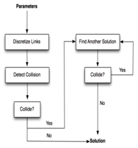
Figure 6 Algorithm for obstacle avoidance.
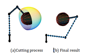
Figure 7 Simulation results.

Conclusion

In this paper a novel anthropomorphic robot was presented with its design and simulation that can successfully peel spherical fruits of varying sizes. The trajectory planning and obstacle avoidance algorithm are proposed to solve potential problems. Having been designed and programmed in a general-purpose manner it can easily be extended for future use cases. With additional work laid out above this could be productionized to kitchens to streamline and speed up workflows. Our future work includes improving and extending the robot presented in this paper in a variety of ways. Improvements contain adding force control, incorporating a feedback system, solving inverse kinematic solution using ANFIS, and applying more resilient obstacle avoidance.14,15 All of these would improve its ability to work in the real world where we will have to account for an imperfect blade, error terms, and arbitrary obstacles. Additionally, the functionality of the robot could be extended. It could be programmed to peel fruit for shapes other than spheres, complete additional tasks, and/or given a second arm to coordinate with the main arm. Given the robot was programmed in a general manner adding support for additional tasks is by design simple, and a second arm would increase utility by allowing the robot to work more autonomously.

Acknowledgements

None.

Conflict of interest

The author declares no conflict of interest.

References

  1. Andy Puzder. Why restaurant automation is on the menu. The wall street journal; 2016.
  2. S Davis. Robotics and automation for the food industry. Food safety magazine. 2014.
  3. Nearly a third of the US food dollar is spent on eating out services. USDA; 2016.
  4. Food Industry Costs, Profits, and Productivity. USDA; 1997.
  5. Productivity and Costs by Industry: wholesale trade, retail Trade, and food services and drinking places industries-2015. bureau of labor statistics; 2015.
  6. Reuben Donado, Lyern Hensed Tan, Don Martin Fernandez, et al. Design, fabrication and testing of a semi-auto green mango peeling machine. International Conference on IEEE; 2015.
  7. Melon slicing device. US Patent; 1958.
  8. Machine for skinning and coring tomatoes. US Patent; 1923.
  9. Riley Don. 3D puma robot demo; 2007.
  10. Mukherjee Ranjan, Mark A Minor, Jay T Pukrushpan. Motion planning for a spherical mobile robot: revisiting the classical ball-plate problem. Journal of Dynamic Systems Measurement, and Control. 2002;124(4):502–511.
  11. Spong Mark W, S Hutchinson, M Vidyasagar. Robot dynamics and control; 2004.
  12. Khatib Oussama. Real-time obstacle avoidance for manipulators and mobile robots. The international journal of robotics research. 1986;5(1):90–98.
  13. Chakravarthy Animesh, Debasish Ghose. Obstacle avoidance in a dynamic environment: A collision cone approach. IEEE Transactions on Systems Man and Cybernetics-Part A: Systems and Humans. 1998;28(5):562–574.
  14. Erol, Duygun, Vishnu Mallapragada, Nilanjan Sarkar. Adaptable force control in robotic rehabilitation. ieee international workshop on robot and human interactive communication; 2005.
  15. Aghajarian Mickael, Kourosh Kiani. Inverse kinematics solution of PUMA 560 robot arm using ANFIS. Ubiquitous robots and ambient intelligence; 2011.
Creative Commons Attribution License

©2017 Hong, et al. This is an open access article distributed under the terms of the, which permits unrestricted use, distribution, and build upon your work non-commercially.